
A Clamp Control Circuit Suitable for Switching Power Chips

A switching power supply chip, control circuit technology, applied in control/regulation systems, electrical components, regulating electrical variables, etc., can solve problems affecting safety and reliability, large overshoot, etc., to achieve complete safety functions and good dynamic response. , the effect of high reliability

Active Publication Date: 2022-01-28
无锡英迪芯微电子科技股份有限公司
View PDF0 Cites 0 Cited by
  • Summary
  • Abstract
  • Description
  • Claims
  • Application Information

AI Technical Summary

Problems solved by technology

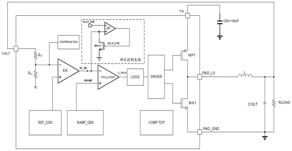
[0006] However, the existing circuit structure has the following disadvantages: when an output short circuit or output overcurrent occurs, the system will reduce the output voltage VOUT by limiting the duty cycle of the power tube switch. At this time, EA will gradually increase VC_EA, The final clamp is at the VCLP_REF voltage. When the output abnormality is released, VC_EA will gradually decrease from VCLP_REF, because VCLP_REF corresponds to the maximum duty cycle, which means that VC_EA will cause a large overshoot of VOUT during the recovery process, which will affect safety. sex and reliability

Method used


Image

  • A Clamp Control Circuit Suitable for Switching Power Chips
  • A Clamp Control Circuit Suitable for Switching Power Chips
  • A Clamp Control Circuit Suitable for Switching Power Chips

Examples


Embodiment Construction

[0027] The specific embodiments of the present invention will be further described below in conjunction with the accompanying drawings.

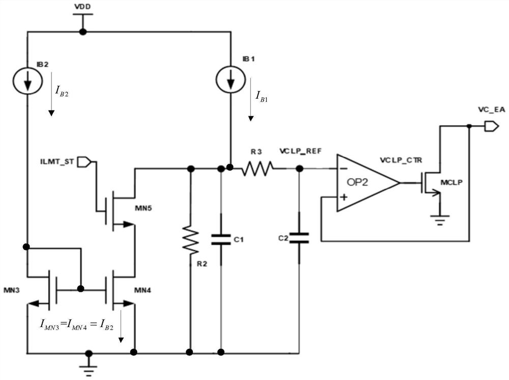
[0028] This application discloses a clamp control circuit suitable for switching power supply chips, please refer to figure 2 , the circuit structure of the switching power supply chip can refer to figure 1 , that is, in the switching power supply chip, the error amplifier EA generates the modulation signal VC_EA to the pulse modulation comparator PWM_COMP according to the output signal OUT of the switching power supply chip and the output reference voltage REF, and the pulse modulation comparator PWM_COMP generates according to the modulation signal VC_EA and the ramp voltage RAMP The square wave signal V_PWM controls and drives the upper tube MP1 and the lower tube MN1 through the driving module, and converts the battery input signal Vin into the corresponding output signal VOUT. The clamp control circuit is connected to the common termin...


PUM


Abstract

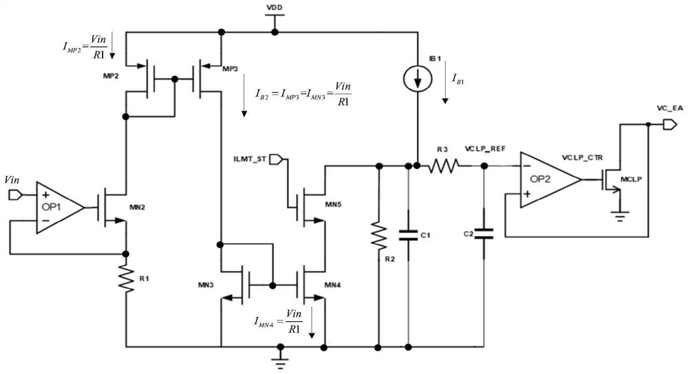
The invention discloses a clamping control circuit suitable for switching power supply chips, and relates to the field of power supply chips. In the clamping control circuit, one end of a mirror current source formed by a third NMOS transistor and a fourth NMOS transistor is connected to a second current source , the other end is connected to the source of the fifth NMOS transistor, the drain of the fifth NMOS transistor is connected to the inverting input end of the second error amplifier circuit to provide a clamping voltage, the gate is controlled by the overcurrent indication signal and the drive transistor is in the It is turned on in an abnormal state, so that the fourth NMOS transistor pulls down the current from the inverting terminal of the second error amplifier circuit to reduce the clamping voltage, thereby avoiding the clamping being fixed and too high when the traditional circuit recovers abnormally, and cannot function. The risk of excessive overshoot voltage at the terminal; the clamp control circuit has good dynamic response, wide application range, complete safety function, sound abnormal protection mechanism, and high reliability, and can be widely used in switching power supply chips.

Description

technical field [0001] The invention relates to the field of power supply chips, in particular to a clamping control circuit suitable for switching power supply chips. Background technique [0002] In consumer electronics and automotive electronics, because electronic components and chips of various specifications have different requirements for power supply, and their energy comes from the battery terminal, it is necessary to use the power supply chip to boost or step down the battery voltage. , so the application of power chips in consumer electronics, industrial electronics and automotive electronics is ubiquitous. [0003] For example, in automotive electronic chips, the input terminal is usually the battery voltage, and its voltage range is about 8V ~ 20V, while the power consumption terminal is usually LED lamp beads, sensor chips, interface chips and main control chips, etc., and its working voltage range is 3V to 5V, so a BUCK (step-down converter) chip is required ...

Claims


Application Information

Patent Timeline
Patent Type & Authority Patents(China)
IPC IPC(8): H02M3/158H02M1/088H02M1/32
CPCH02M3/158H02M1/088H02M1/32
Inventor 董渊李响蔡胜凯张军庄健
Owner 无锡英迪芯微电子科技股份有限公司
Learn More