Polishing device on light conveying belt production line

A light-duty conveyor belt and production line technology, applied in the direction of grinding drive device, grinding/polishing safety device, grinding machine, etc., can solve the problems such as the inability to control the grinding degree of the conveyor belt surface, the contamination of the working environment by flying debris, etc., and increase the range of motion , Healthy working environment, stable grinding effect

Active Publication Date: 2021-06-22
江苏博顺带业有限公司
View PDF6 Cites 2 Cited by
  • Summary
  • Abstract
  • Description
  • Claims
  • Application Information

AI Technical Summary

Problems solved by technology

[0003] Therefore, the field of conveyor belt processing is also constantly developing. Grinding light conveyor belts is also a kind of conveyor belt processing. It will also produce a lot of flying debris that will pollute the working environment;

Method used


Image

  • Polishing device on light conveying belt production line
  • Polishing device on light conveying belt production line
  • Polishing device on light conveying belt production line

Examples


Embodiment 1

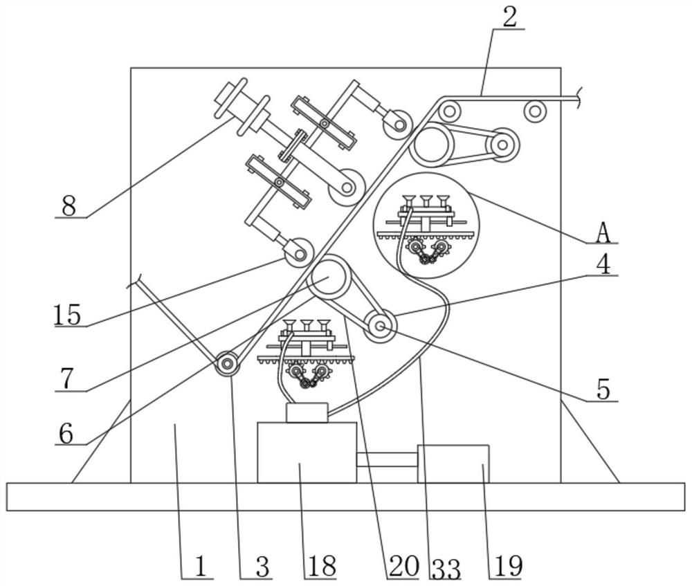
[0027] see figure 1 , figure 2 , image 3 , Figure 4 , Figure 6 and Figure 7 , a grinding device on a light conveyor belt production line, comprising a fixed frame 1; a sanding roller 7; and a cylinder 8; the fixed frame 1 is fixedly connected with a first motor 4, and the output shaft of the first motor 4 is fixedly connected There is a first pulley 5, and a second pulley 6 is also rotatably connected to the fixed frame 1, and the second pulley 6 is fixedly connected with the grinding roller 7, and the first pulley 5 and the second pulley 6 are connected through the transmission of the first belt 20;

[0028] Also be fixedly connected with cylinder 8 on described fixed mount 1, on described fixed mount 1, also be installed with pinching roller 9 by mounting seat rotation, the piston rod of described cylinder 8 is fixedly connected with the mounting seat on pinching roller 9;

[0029] Wherein, the pinch roller 9 is rotatably installed on the mounting seat, and the mo...

Embodiment 2

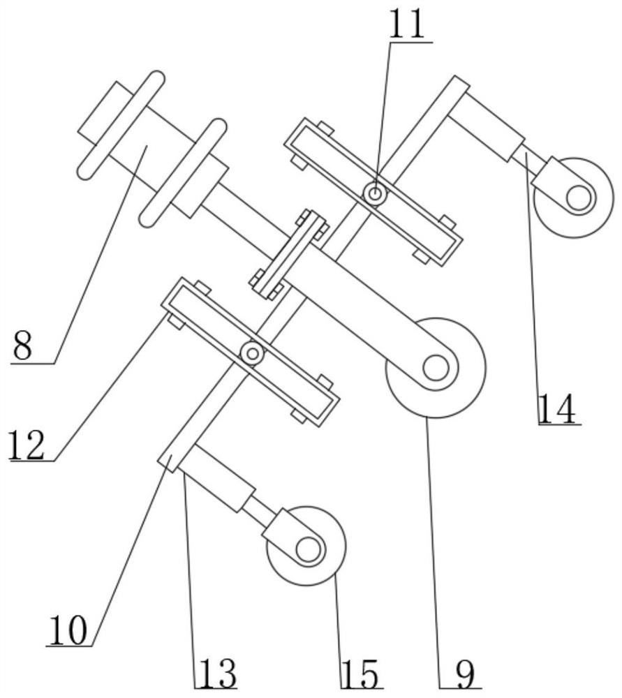
[0049] As a preferred solution of Embodiment 1, please refer to figure 1 , figure 2 and Figure 5 , both ends of the mounting seat on the pressure roller 9 are fixedly connected with a fixed plate 10, one end of the fixed plate 10 is fixedly connected with a sleeve 13, and a sleeve rod 14 is slidably connected in the sleeve 13, so The sleeve rod 14 is fixedly connected with the mounting frame on the adjustment wheel 15 after passing through the sleeve pipe 13, and one end of the sleeve rod 14 is also fixedly connected with a slide plate 17, and the sleeve rod 14 is also sleeved with a spring 16, and the The two ends of the spring 16 are respectively fixedly connected with the slide plate 17 and the inner wall of the casing 13;

[0050] Wherein, the spring 16 can absorb the shock generated when the conveyor belt body 2 is polished;

[0051] Wherein, the adjustment wheel 15 is rotatably installed on the fixed mount 1, and the fixed mount 1 is fixedly connected with the cover...

Embodiment 3

[0055] As a preferred solution of Embodiment 1 or Embodiment 2, please refer to figure 1 and figure 2 , on the fixed plate 10, a slide block 11 is also rotatably installed, and the position of the slide block 11 corresponding to the fixed plate 10 is also fixedly connected with a rectangular frame 12, and the slide block 11 is slidably connected to the rectangular frame 12;

[0056] Wherein, the slider 11 is a cylindrical structure;

[0057] Working principle: When the piston rod of the cylinder 8 drives the pressure roller 9 to move, the fixed plate 10 drives the slider 11 to slide in the rectangular frame 12, which guides the piston rod of the cylinder 8 and makes the pressure roller 9 move more smoothly. smooth.


PUM


Abstract

The invention relates to a polishing device on a light conveying belt production line. The polishing device comprises a fixing frame, a polishing roller and a cylinder, wherein the fixing frame is fixedly connected with a first motor, an output shaft of the first motor is fixedly connected with a first belt wheel, the fixing frame is further rotationally connected with a second belt wheel, the second belt wheel is fixedly connected with the polishing roller, and the first belt wheel and the second belt wheel are in transmission connection through a first belt; the cylinder is further fixedly connected to the fixing frame, and a pressing roller is further rotationally mounted on the fixing frame through a mounting base; by adjusting the rotating speed of the polishing roller and the pressure of the pressing roller, the surface or the back face of a conveying belt body can be ground to different degrees, the functionality of the equipment is improved, a rack drives a sliding base and a suction nozzle to slide in a reciprocating mode, and therefore the movement range of the suction nozzle can be increased, flying chips produced by polishing can be fully sucked by the suction nozzle, and a working environment is healthier.

Description

technical field [0001] The invention relates to the field of conveyor belt production equipment, in particular to a grinding device on a light conveyor belt production line. Background technique [0002] Conveyor belt, also known as conveyor belt, is a device that transfers goods through belts. In industrial production, the use of conveyor belts is particularly important. In industries, conveyor belts are often used in occasions where the conveying volume is small and the conveying distance is short , greatly improve the efficiency of industrial production, save manpower, and are widely used by people; the domestic light conveyor belt industry has made great progress, and the quality of some light conveyor belts has been equal to that of similar foreign products. Light conveyor belts mainly include PVC light conveyor belts, rubber and plastic products light conveyor belts, PU light conveyor belts, etc.; [0003] Therefore, the field of conveyor belt processing is also const...

Claims


Application Information

Patent Timeline
Patent Type & Authority Applications(China)
IPC IPC(8): B24B7/12B24B27/00B24B41/00B24B41/06B24B47/00B24B55/06
CPCB24B7/12B24B27/0076B24B41/06B24B41/007B24B47/00B24B55/06
Inventor 袁宏文李文武李文华冯海军
Owner 江苏博顺带业有限公司
Why Eureka
Try Eureka