Industrial sewage purification device for environmental protection engineering

A technology for industrial sewage and purification devices, which is applied in water/sewage treatment, water/sewage multi-stage treatment, water/sludge/sewage treatment, etc. It can solve the problems of complex overall structure, poor sewage filtration effect, and many additions. To achieve the effect of good cleaning effect and simple structure

Inactive Publication Date: 2021-06-22
徐瑞
View PDF10 Cites 5 Cited by
  • Summary
  • Abstract
  • Description
  • Claims
  • Application Information

AI Technical Summary

Problems solved by technology

[0005] 1. The traditional sewage purification device has a poor filtering effect on sewage. Although the above-mentioned device can clean the filter screen, not only the cleaning effect is poor, but the overall structure is also relatively complicated, and the cleaned debris is not convenient for unified recycling. ;
[0006] 2. Traditional sewage purification devices often use water purification particles such as activated carbon to adsorb sewage in the pipeline, but the water purification particles traverse the pipeline, and the water purification particles will slide to both sides under the impact of sewage, resulting in water purification particles Inability to fully contact with sewage;
[0007] 3. Traditional sewage purification devices often add sewage purification agents to sewage to treat sewage, but they cannot automatically control the amount of chemicals added according to the flow of sewage, and often add too little or too much chemicals

Method used


Image

  • Industrial sewage purification device for environmental protection engineering
  • Industrial sewage purification device for environmental protection engineering
  • Industrial sewage purification device for environmental protection engineering

Examples


Embodiment Construction

[0047] The following will clearly and completely describe the technical solutions in the embodiments of the present invention with reference to the accompanying drawings in the embodiments of the present invention. Obviously, the described embodiments are only some, not all, embodiments of the present invention. Based on the embodiments of the present invention, all other embodiments obtained by persons of ordinary skill in the art without making creative efforts belong to the protection scope of the present invention.

[0048] In the description of the present invention, it should be noted that the orientation or positional relationship indicated by the terms "vertical", "upper", "lower", "horizontal" etc. is based on the orientation or positional relationship shown in the drawings, and is only In order to facilitate the description of the present invention and simplify the description, it does not indicate or imply that the device or element referred to must have a specific o...


PUM


Abstract

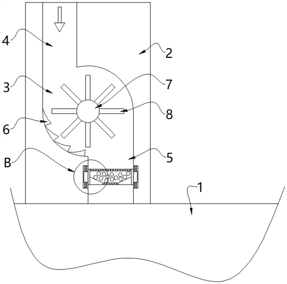
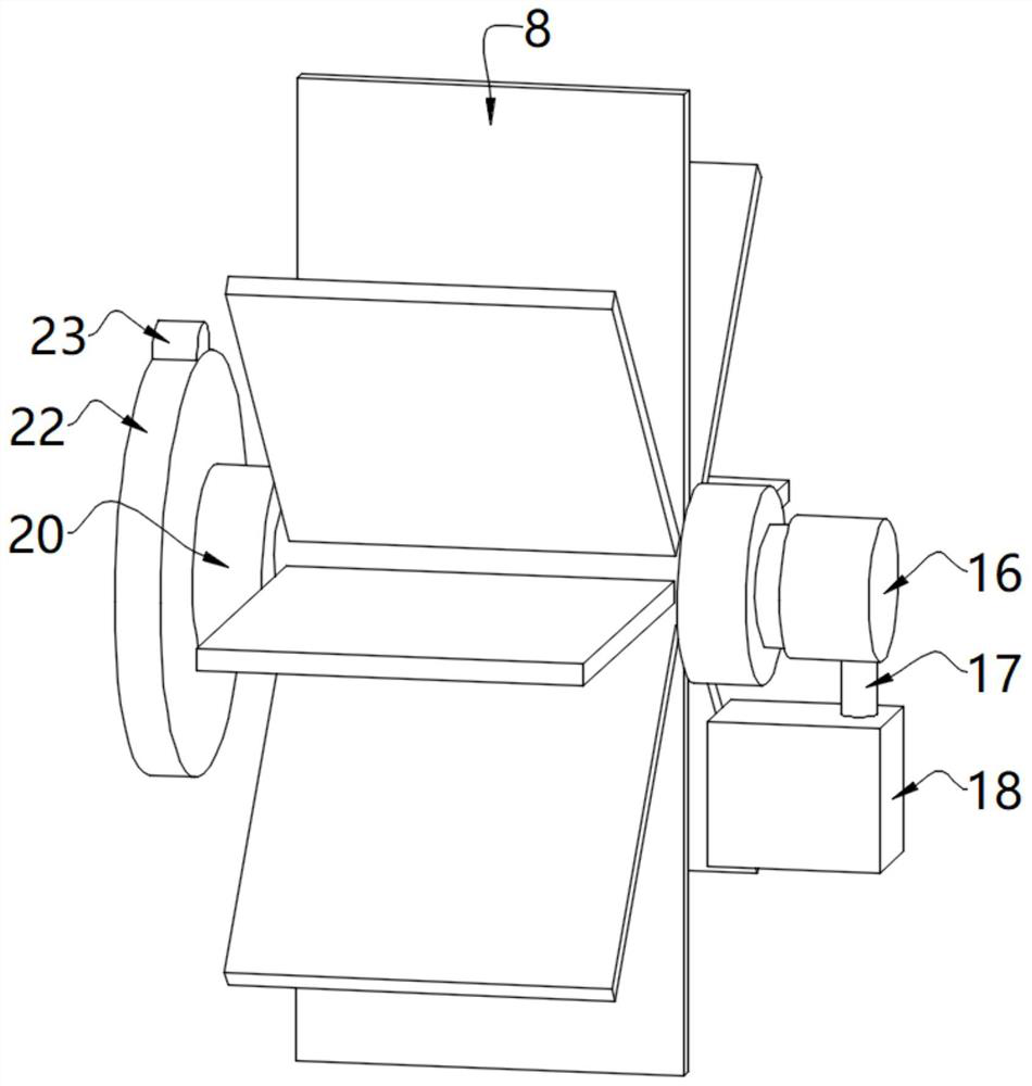
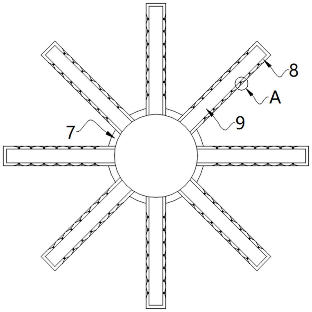
The invention relates to the technical field of industrial sewage purification, and discloses an industrial sewage purification device for environmental protection engineering, the industrial sewage purification device comprises a purification device main body, a water inlet pipe is fixedly mounted at the top of the purification device main body, and a water inlet groove, a driving cavity and a water outlet groove are formed in the water inlet pipe from top to bottom in sequence in a penetrating manner; a rotating shaft is internally rotated in the driving cavity, and blades are evenly and fixedly installed on the outer wall of the rotating shaft. When industrial sewage hits the blades, the sewage flows through the sewage collecting grooves and the communicating grooves in the blades, particles in the sewage enter the containing cavity through the sewage collecting grooves and the communicating grooves and cannot be discharged, and when the blades rotate to the upper half part of the rotating shaft, the particles in a containing cavity fall into the inner cavity from the containing cavity, the particles fall into the inner cavity, meanwhile, the rotating shaft also rotates, the rotating shaft rotates to guide the particles to move towards the open end of the inner cavity through the guide blades, finally the particles fall into the storage box through a clamping sleeve and a vertical cylinder, and unified collection of the particles is completed.

Description

technical field [0001] The invention relates to the technical field of industrial sewage purification, in particular to an industrial sewage purification device for environmental protection engineering. Background technique [0002] Industrial wastewater includes production wastewater, production sewage and cooling water. It refers to wastewater and waste liquid produced in the process of industrial production, which contains industrial production materials, intermediate products, by-products and pollutants produced in the production process lost with water. Since industrial wastewater contains a variety of toxic substances, polluting the environment is very harmful to human health. Therefore, it is necessary to develop comprehensive utilization, turn harm into benefit, and take corresponding purification measures for disposal according to the pollutant composition and concentration in the wastewater. can be discharged. [0003] The Chinese patent announcement number is: th...

Claims


Application Information

Patent Timeline
Patent Type & Authority Applications(China)
IPC IPC(8): C02F9/04
CPCC02F9/00C02F1/5281C02F1/283C02F1/001C02F1/00
Inventor 徐瑞
Owner 徐瑞
Why Eureka
Try Eureka