
Soil body motion posture monitoring box

A movement attitude and soil technology, applied in the field of soil movement attitude monitoring box, can solve the problems of inaccurate monitoring results, high economic and labor costs, and great influence of human factors, so as to achieve hanging storage, improve monitoring accuracy, Stable and long-term monitoring effect

Active Publication Date: 2021-06-22
GUILIN UNIV OF ELECTRONIC TECH
View PDF21 Cites 0 Cited by
  • Summary
  • Abstract
  • Description
  • Claims
  • Application Information

AI Technical Summary

Problems solved by technology

The difficulties in soil deformation and displacement monitoring are: 1. The monitoring box needs to move with the soil to truly reflect the displacement and deformation of the soil; 2. The monitoring box deployed in the soil needs external communication. The body shields the communication signal and consumes a lot of power. If the wired form is used, the cable will pull the monitoring box, causing the monitoring box to fail to reflect the real displacement and deformation of the soil; 3. The long-term existence of groundwater in the soil will not only affect The normal operation of the electronic monitoring equipment will also generate buoyancy to the monitoring box, making the monitoring results inaccurate; 4. It is difficult to deploy the monitoring box in deep soil, and the deployment depth is difficult to control
[0003] In the prior art, an inclinometer is used to monitor the displacement of the soil, but it can only monitor the horizontal displacement of the soil, and cannot fully monitor the overall movement posture of the soil; in addition, the inclinometer is generally used for manual data collection, and human factors Large impact, unable to automatically output, calculate, and analyze data in real time, high economic and labor costs

Method used


Image

  • Soil body motion posture monitoring box
  • Soil body motion posture monitoring box
  • Soil body motion posture monitoring box

Examples


Embodiment

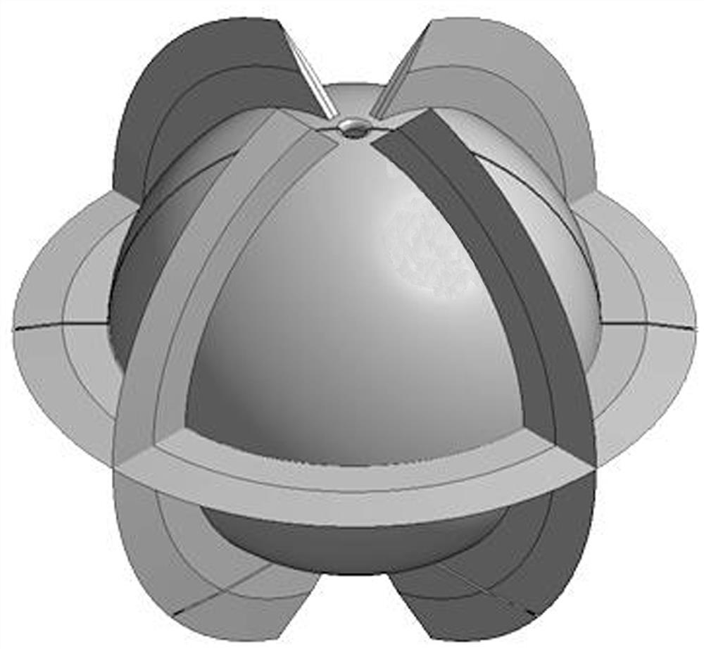
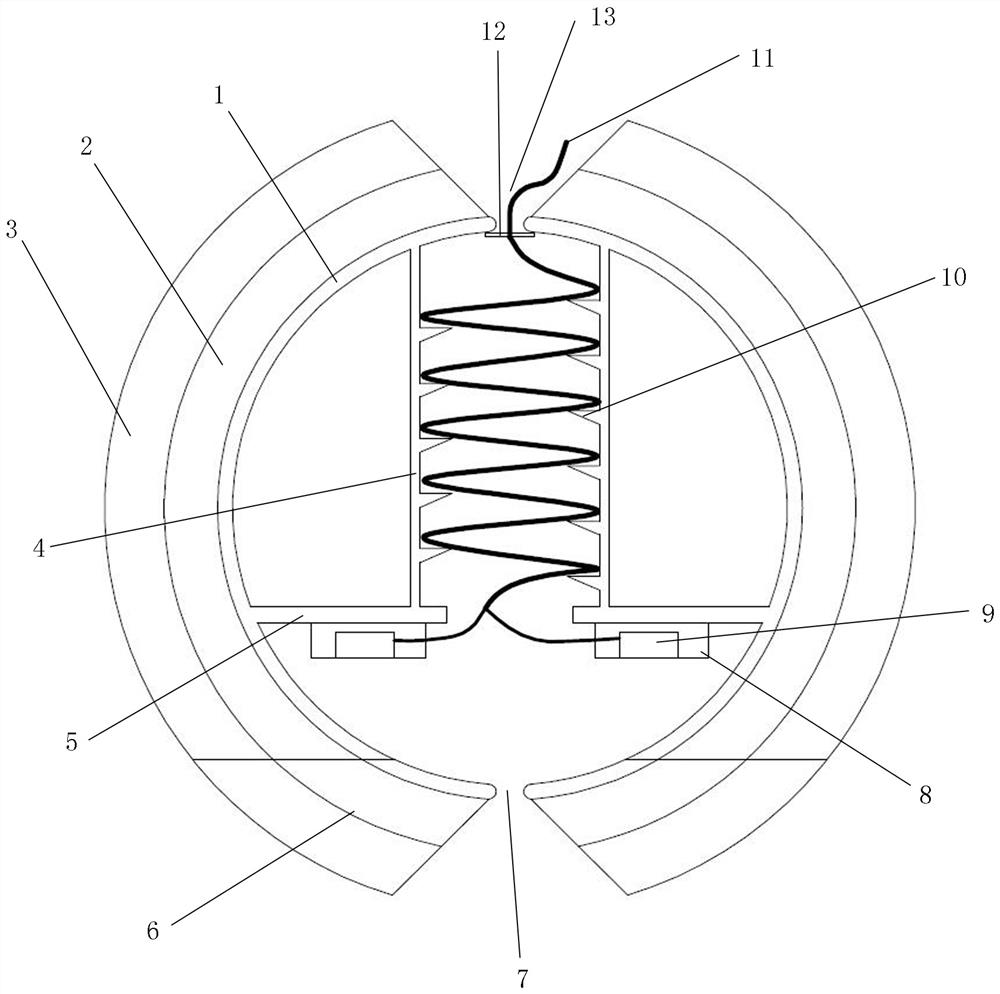
[0031] Such as figure 1 , figure 2 Shown:

[0032] A soil motion attitude monitoring box, comprising a hollow sphere 1, a sealing box 8, and an attitude angle sensor 9; the upper end of the hollow sphere 1 is provided with an upper outlet hole 13, and the lower end is provided with a detachable bottom cover 6, and the bottom cover 6 is provided with The lower outlet hole 7, the middle and lower part of the hollow sphere 1 is provided with an annular platform 5, and a cylindrical hollow cylinder 4 is arranged on the annular platform 5. The top of the cylinder 4 is connected with the sphere 1, and the bottom of the cylinder 4 is connected with the annular platform. 5. The edges of the inner ring are connected as a whole, and the cavity in the hollow cylinder 4 communicates with the upper outlet hole 13 and the lower outlet hole 7, and the cylinder 4 is provided with an internally threaded wire setting table 10;

[0033] Two sealed boxes 8 are symmetrically fixed on the bottom...


PUM


Abstract

The invention discloses a soil body motion posture monitoring box which comprises a hollow sphere, a sealing box and a posture angle sensor. The upper end of the hollow sphere is provided with an upper wire outlet hole, the lower end of the hollow sphere is provided with a bottom cover, the bottom cover is provided with a lower wire outlet hole, the middle lower portion in the hollow sphere is provided with an annular platform, a columnar hollow cylinder is arranged on the annular platform, the top of the cylinder is connected with the sphere into a whole, and the bottom of the cylinder is connected with the inner ring edge of the annular platform into a whole. A cavity in the hollow cylinder is communicated with the upper wire outlet hole and the lower wire outlet hole, and a wire placing table in an internal thread shape is arranged in the cylinder; the sealing boxes are fixed to the bottom of the annular platform, the two posture angle sensors are fixed in the two sealing boxes respectively, and power source signal lines connected with the posture angle sensors are led out of the sealing boxes, then wound on the threaded wire placing table in the cylinder and led out of the ball body from the upper line outlet hole. The power supply signal wire at the upper wire outlet hole is fixed on the upper wire outlet hole through water-soluble glue. The monitoring box is simple and convenient to operate, accurate in measurement, convenient to transport, repair and maintain and low in monitoring cost.

Description

technical field [0001] The invention relates to the technical field of geotechnical engineering monitoring, in particular to a soil movement posture monitoring box. Background technique [0002] Deformation and displacement monitoring occupies an extremely important position in the quality and safety control of engineering construction. The existing space motion attitude monitoring technology is mostly applied to the structures above the ground, and cannot be applied to the deformation and displacement monitoring of the soil below the ground. However, excessive soil displacement and deformation are often the root causes of engineering accidents, such as foundation pit collapse, road surface subsidence, uneven foundation settlement, and slope instability. The difficulties in soil deformation and displacement monitoring are: 1. The monitoring box needs to move with the soil to truly reflect the displacement and deformation of the soil; 2. The monitoring box deployed in the so...

Claims


Application Information

Patent Timeline
Patent Type & Authority Applications(China)
IPC IPC(8): G01B21/00G01B21/02G01B21/22
CPCG01B21/00G01B21/02G01B21/22
Inventor 吴迪高子锋蔺文博王金晨娄万鹏程峰黄宇唐咸远吴远斌
Owner GUILIN UNIV OF ELECTRONIC TECH
Learn More