Shadow rendering method and device and electronic equipment

A shadow and current position technology, applied in the field of shadow rendering, can solve problems such as unsupported object movement or light source movement, and achieve the effect of saving calculation and improving effect

Active Publication Date: 2021-06-22
北京壳木软件有限责任公司
View PDF14 Cites 5 Cited by
  • Summary
  • Abstract
  • Description
  • Claims
  • Application Information

AI Technical Summary

Problems solved by technology

When rendering an object, you can directly sample and bake the texture to obtain shadow information. The overhead is very small

Method used


Image

  • Shadow rendering method and device and electronic equipment
  • Shadow rendering method and device and electronic equipment
  • Shadow rendering method and device and electronic equipment

Examples


Embodiment Construction

[0029] The technical solutions in the embodiments of the present application will be described below with reference to the drawings in the embodiments of the present application.

[0030] It should be noted that like numerals and letters denote similar items in the following figures, therefore, once an item is defined in one figure, it does not require further definition and explanation in subsequent figures. Meanwhile, in the description of the present application, the terms "first", "second" and the like are only used to distinguish descriptions, and cannot be understood as indicating or implying relative importance.

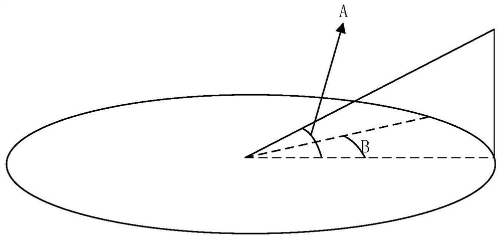
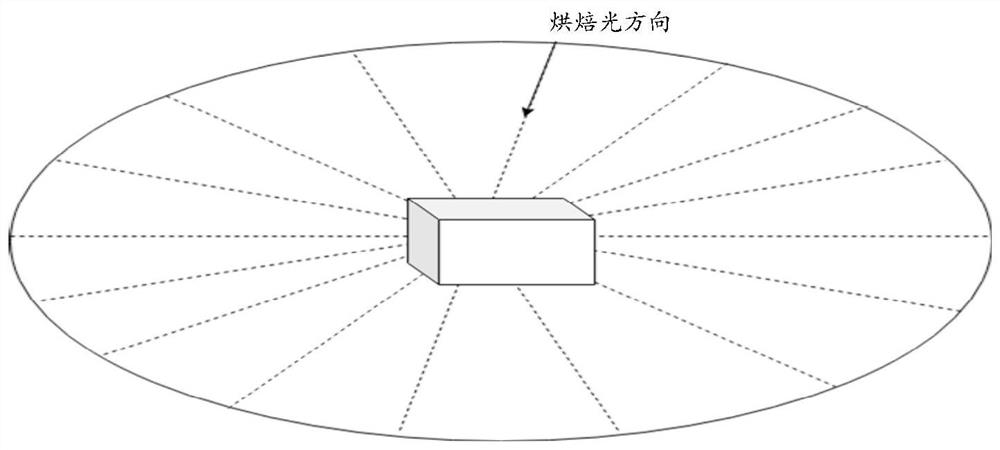
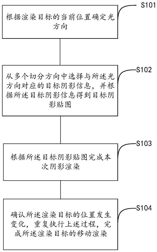
[0031] The implementation process of the embodiment of the present application can be divided into two stages. The first stage is the data preparation stage, which is to obtain shadow information of multiple segmentation directions. The second stage is to obtain the light direction determined by the current position of the rendering target. According to The li...


PUM


Abstract

Embodiments of the invention provide a shadow rendering method and device, and electronic equipment. The method comprises the steps of determining a light direction according to a current position of a rendering target; selecting target shadow information corresponding to the light direction from multiple segmentation directions, acquiring a target shadow map according to the target shadow information, wherein the segmentation direction corresponding to the target shadow information is the segmentation direction closest to the light direction; completing the shadow rendering according to the target shadow map; and confirming that the position of the rendering target is changed, and repeating the process to complete the mobile rendering of the rendering target. According to some embodiments of the application, the rendering of the moving object is realized based on the pre-stored hard shadow information of each segmentation direction, so that the calculation amount is saved, and the shadow rendering effect of the embedded terminal on the moving object is improved.

Description

technical field [0001] The present application relates to the field of game development, and specifically, the embodiments of the present application relate to a shadow rendering method, device and electronic equipment. Background technique [0002] Shadows are very important to improve the realism of rendered objects in games. At present, the popular technologies mainly include the following: The first one, casting shadows, is to first render the shadows from the perspective of the light source to the occluder to get the shadows, and then project them to the shadow receiving objects (receiver), so that Apply shadows to uneven surfaces. The disadvantage of this method is that the occluder and receiver need to be clearly known, and the shadow of the occluder itself cannot be rendered, so it can only be applied to simple scenes. The second, shadow depth map (ShadowMap) is a commonly used method for generating real-time shadows. It takes the position of the light source as t...

Claims


Application Information

Patent Timeline
IPC IPC(8): G06T15/60G06T15/00G06T15/04A63F13/52A63F13/60
CPCG06T15/60G06T15/005G06T15/04A63F13/52A63F13/60Y02D10/00
Inventor 易律
Owner 北京壳木软件有限责任公司
Why Eureka
Try Eureka