Ductus venosus flushing device

A technology for flushing devices and venous catheters, which is applied to catheters and devices introduced into the body. It can solve the problems of increasing the risk of catheter failure due to thrombosis, and achieve the effect of improving the cleaning effect and applicable surface, easy to clean, and simple and convenient to maintain.

Active Publication Date: 2021-06-25
WEST CHINA HOSPITAL SICHUAN UNIV
View PDF6 Cites 1 Cited by
  • Summary
  • Abstract
  • Description
  • Claims
  • Application Information

AI Technical Summary

Problems solved by technology

It is mentioned that "irregular flushing and sealing operat

Method used


Image

  • Ductus venosus flushing device
  • Ductus venosus flushing device
  • Ductus venosus flushing device

Examples


Embodiment 1

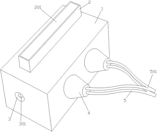
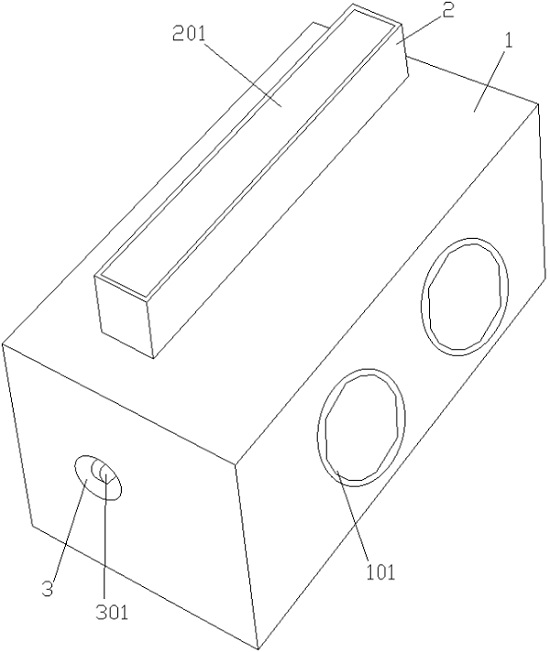
[0069] Such as Figure 1 to Figure 4 As shown, a venous catheter flushing device includes a square box 1, the top of the box 1 is provided with a stamping module 2, the stamping module 2 is a protruding tubular structure on the box 1, the stamping module 2 and the inside of the box 1 In communication, a button 201 is provided inside the stamping module 2 . The raised stamping module 2 on the box body 1 provides a longer sliding stroke for the button 201. The button 201 is embedded in the stamping module 2 of the tubular structure to keep the stability when the button 201 is pressed. The structure of the stamping module 2 keeps the button 201 While pressing stability, it also saves internal space.

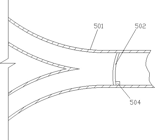
[0070] The side of the box body 1 is provided with a stop ring 101, and the pulse pump body is threadedly connected with the stop ring 101, which is convenient for disassembly and disinfection after use. The pulse pump body is connected with a direct current inlet pipe 501 and a p...

Embodiment 2

[0075] Such as Figure 5 As shown, in this embodiment, the button 201 is connected with the rack 7 and the spring 9 . The stamping module 2 is provided with a resilient panel 202, and the rack 7 passes through the resilient panel 202 to drive the reciprocating mechanism to rotate. The spring 9 is connected between the button 201 and the rebound panel 202 , and after the button 201 is pressed, the spring 9 resets the reaction force of the rebound panel 202 to assist the button 201 .

[0076] The spring 9 is sheathed on the spring sleeve rod 901 , and the spring sleeve rod 901 passes through the rebound panel 202 and is flexibly connected with the rebound panel 202 . The spring sleeve rod 901 prevents the spring 9 from deforming and bending to the side after being compressed, so as to avoid the springback aging of the spring 9 . A plurality of springs 9 are connected to the button 201 to ensure that the force is evenly distributed when the button 201 is pressed, and the button...

Embodiment 3

[0080] Such as Figure 6 to Figure 10 shown, where Figure 7 Among them, c is the inner cover 401 , d is the diaphragm nut 404 , e is the flexible diaphragm 402 , f is the diaphragm screw 403 , and g is the outer cover 4 .

[0081] In this embodiment, the pulse pump body includes an outer cover 4 and an inner cover 401, the outer cover 4 and the inner cover 401 are trumpet-shaped, and the two ends with larger diameters are screwed together, and the inner cover 401 is screwed on the box body 1, and the inner cover The staggered platform 4012 and the transmission hole 4011 are provided on the 401, and the flexible diaphragm 402 is clamped between the outer cover 4 and the staggered platform 4012 of the inner cover 401. Large surface area provides room for expansion and contraction. At the same time, in order to ensure that the physiological saline used for flushing is completely discharged, the flexible diaphragm 402 is completely attached to the inner wall of the outer cover ...


PUM


Abstract

The invention discloses a ductus venosus flushing device. The ductus venosus flushing device comprises a box body and a stamping module, wherein the stamping module is arranged at the top part of the box body, a stop ring is arranged on the side face of the box body, a pulse pump body is in threaded connection with the interior of the stop ring, and a direct current inlet pipe and a pulse outlet pipe are connected to the pulse pump body; the stamping module is of a tubular structure protruding from the box body, and a button is movably arranged in the stamping module; a cavity is formed in the pulse pump body, a flexible diaphragm is arranged in the cavity to divide the cavity into two cavity bodies, and one cavity body is communicated with the direct current inlet pipe and the pulse outlet pipe; and a reciprocating mechanism is arranged in the box body, the reciprocating mechanism is respectively connected with a button and a flexible diaphragm, under the pushing of the button, the reciprocating mechanism drives the flexible diaphragm to move back and forth to generate negative pressure in the pulse pump body, and multi-phase variable-frequency pulse is realized through a gear shifting mechanism.

Description

technical field [0001] The invention relates to the field of medical equipment, in particular to a venous catheter flushing device. Background technique [0002] Commonly used clinical venous catheters mainly include: peripheral venous catheter (PVC), peripherally inserted central catheter (PICC), central venous catheter (CVC), infusion port (PORT) and so on. Clinical venous catheter maintenance mainly includes flushing and sealing, dressing replacement, catheter fixation, puncture site protection, medical adhesive-related skin injuries, infusion connectors, catheter removal, education and training, infection management, complications, etc. [0003] With the increasing clinical application of various infusion catheters, the incidence of venous thrombosis associated with infusion catheters has increased significantly. It is a special type of venous thromboembolism, and its etiology is closely related to the implanted catheter. Improper understanding and handling of it will i...

Claims


Application Information

Patent Timeline
IPC IPC(8): A61M5/14A61M25/00
CPCA61M5/14A61M25/00A61M2005/1403A61M2025/0019
Inventor 刘光娣田永明余荷唐荔刘洪霞丁乾容刘常清蒋婷
Owner WEST CHINA HOSPITAL SICHUAN UNIV
Why Eureka
Try Eureka