

Blood collection tube blending device
A blood collection and mixing technology, applied in the field of medical devices, can solve the problems of time-consuming and many steps, different shaking amplitudes and times, sore arms of medical staff, etc., and achieves simple and convenient maintenance, good mixing effect, and improved The effect of flexibility
- Summary
- Abstract
- Description
- Claims
- Application Information
AI Technical Summary
Problems solved by technology
Method used
Image

Examples
Embodiment 1
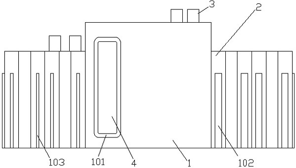
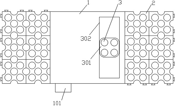
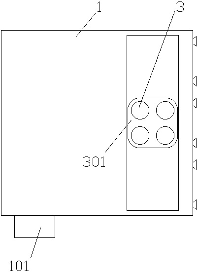
[0063] Such as figure 1 , figure 2 and Figure 19 As shown, a blood collection tube mixing device is characterized in that: it includes a mixing box 1 and a storage module 2, and the mixing box 1 and the storage module 2 are equipped with an expansion bar 102 and an expansion slot 103, and the expansion bar 102 is a horizontal The cross-section is trapezoidal strip shape, and the expansion slot 103 is in the shape of a groove matched with the expansion strip 102, which is convenient for interlocking. The storage module 2 is provided with a plurality of storage holes 201 for storing the blood collection tubes 3 , which is convenient for placing the blood collection tubes 3 .
[0064] In the present application, the extension bars 102 and the extension slots 103 are arranged on both sides of the mixing box 1 respectively, and the extension bars 102 and the extension slots 103 of the storage module 2 are symmetrically distributed on the sides. It can also be adjusted accordin...
Embodiment 2
[0068] In this example, if Figure 4 to Figure 14 As shown, the mixing mechanism includes a first transmission surface 503, a second transmission surface 604, a third transmission surface 901 and a driving surface 401; the button 4 is connected to the driving surface 401 through a spring sleeve rod 402, and the first The driving surface 503 is provided with a driving shaft 601, and one end of the driving shaft 601 is connected with a driving gear 502, and the driving gear 502 is connected with the driving rack 5, and one end of the driving rod 5 passes through the driving surface 401 and the button 4 through the connecting rod 501. The other end is connected with the inside of the mixing box 1 through the spring sleeve rod 402 .
[0069] The other end of the drive shaft 601 passes through the first transmission surface 503 and is connected with the barrel 61 and the amplifying gear 6 . Wherein, the amplifying gear 6 is connected with the drive shaft 601 through a ratchet. Th...
Embodiment 3
[0075] Such as Figure 6 As shown, in this embodiment, the drive rack 5 is connected in a ring shape, the upper and lower surfaces inside the ring are tangent to the drive gear 502 , and a rack portion 504 is provided on one side of the drive rack 5 . Such a structure makes the combination of the driving gear bar 5 and the driving gear 502 more stable, and the vibration of the mechanism is small to avoid tooth skipping.
PUM
 Abstract
Description
Claims
Application Information