Supercharge Your Innovation With Domain-Expert AI Agents!

Cleaning device for gear processing

A technology for cleaning devices and gears, which is applied to cleaning methods using liquids, cleaning methods using tools, cleaning methods and utensils, and can solve problems such as inability to clean gears, lack of cleanliness of gears, and high residual rate of old oil. Achieve the effect of improving cleaning effectiveness, improving cleaning efficiency, and stable and reliable use

Active Publication Date: 2022-07-12
CHONGQING WANGCHENG TECH
View PDF10 Cites 0 Cited by
  • Summary
  • Abstract
  • Description
  • Claims
  • Application Information

AI Technical Summary

Problems solved by technology

[0002] A gear is a mechanical element with teeth on the rim that can continuously mesh to transmit motion and power. A gear is a mechanical part with teeth that can mesh with each other. After meshing, each gear can transmit power. During the processing, in order to process more smoothly , some lubricating oil will be used to coat the gears, and then processed. After the processing is completed, the gears will produce some waste chips. Most of the waste chips can be carried by the lubricating oil, but a small part is still adhered to the gears; The common treatment method is to replace the lubricating oil in the device to achieve the purpose of cleaning the gears. The lubricating oil has the characteristics of high viscosity and poor fluidity, so that the sludge and oil in the box cannot be cleaned, and the residual oil is not completely discharged. That is to say, the residual rate of old oil in the gearbox is relatively high, and the cleaning of the gears is not thorough at the same time
[0003] When cleaning, the above cleaning methods cannot fully clean the gears, especially at the root of the tooth surface of the gears, impurities are likely to remain, resulting in uneven cleaning, so that the cleanliness of the gears cannot be achieved, and the cleaning In this case, the gears are prone to collisions, causing wear and tear and affecting the quality of the gears, so the applicability and practicability are limited.

Method used


Image

  • Cleaning device for gear processing

Examples


Embodiment 1)

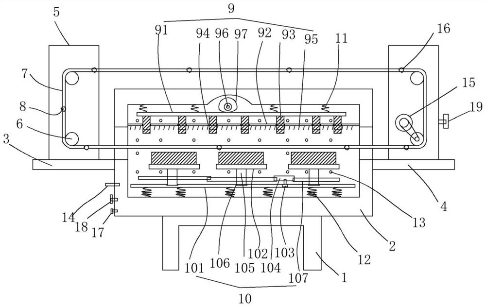
[0017] figure 1 An embodiment of the invention is shown in which figure 1 It is a schematic diagram of the structure of the present invention.

[0018] See figure 1 , a cleaning device for gear processing, comprising a base 1, a cleaning casing 2 is fixed on the base, a feeding platform 3 is opened on one side of the cleaning casing, and the other end of the cleaning casing is A discharge platform 4 is opened, a support plate 5 is fixed on the side of the feed platform and the discharge platform, a rotating shaft 6 is fixed on the support plate, and a transmission chain 7 is arranged between the rotating shafts. The side of the chain is fixed with a shaft 8 for connecting to the shaft hole in the center of the gear. The lower part of the transmission chain passes through the interior of the cleaning housing, and an upper cleaning structure is provided on the top wall of the cleaning housing. 9. A lower cleaning structure 10 is arranged on the bottom wall of the cleaning hou...


PUM


Abstract

The invention discloses a cleaning device for gear processing, which comprises a base, a cleaning casing is fixed on the base, a feeding platform is arranged on one side of the cleaning casing, and a discharging platform is arranged on the other end of the cleaning casing. A supporting plate is fixed on the side of the feeding platform and the discharging platform, a rotating shaft is fixed on the supporting plate, a conveying chain is arranged between the rotating shafts, and the side of the conveying chain is fixed with a shaft hole for connecting to the center of the gear. The shaft rod is provided with an upper cleaning structure on the top wall of the cleaning shell, and a lower cleaning structure is arranged on the bottom wall of the cleaning shell, an upper buffer spring is fixed between the upper cleaning structure and the top wall of the cleaning shell, A lower buffer spring is fixed between the cleaning structure and the bottom wall of the cleaning casing, and a cleaning liquid spray head is evenly fixed on the inner wall of the cleaning casing. The structure of the invention is reasonable in arrangement, which is beneficial to improve the cleaning efficiency and the cleaning effectiveness, and has strong applicability and good practicability.

Description

technical field [0001] The invention belongs to the technical field of gear processing equipment, and particularly relates to a cleaning device for gear processing. Background technique [0002] Gears are mechanical components with teeth on the rim that can continuously mesh to transmit motion and power. Gears are mechanical parts with teeth that can mesh with each other. After meshing, each gear can transmit power. In the processing process, in order to process more smoothly. , some lubricating oil will be used to coat the gears, and then they will be processed. After the processing is completed, the gears will generate some waste chips. Most of the waste chips can be carried by the lubricating oil, but a small part is still adhered to the gears; In the common treatment method, the lubricating oil in the device is replaced to achieve the purpose of cleaning the gears. The lubricating oil has the characteristics of high viscosity and poor fluidity, which makes the sludge and...

Claims


Application Information

Patent Timeline
Patent Type & Authority Patents(China)
IPC IPC(8): B08B3/02B08B1/02B08B13/00B08B1/20
CPCB08B3/02B08B13/00B08B1/20B08B1/12Y02P70/10
Inventor 包海平
Owner CHONGQING WANGCHENG TECH
Features
  • R&D
  • Intellectual Property
  • Life Sciences
  • Materials
  • Tech Scout
  • Unparalleled Data Quality
  • Higher Quality Content
  • 60% Fewer Hallucinations
Learn More