
Nano hard alloy micro-drill bar production system

A cemented carbide, production system technology, applied in the direction of metal extrusion dies, etc., can solve the problems of easy blockage, high friction, mold wear, etc., to avoid blockage, reduce pressure, and improve quality.

Pending Publication Date: 2021-06-25
蓬莱市超硬复合材料有限公司
View PDF0 Cites 0 Cited by
  • Summary
  • Abstract
  • Description
  • Claims
  • Application Information

AI Technical Summary

Problems solved by technology

[0003] Existing molds for processing alloy rods, when in use, the rods in the cavity cannot fall off automatically due to the large friction between itself and the inner wall of the mold cavity; The friction between the material for making bar alloy and the lower end of the loading cavity is relatively large, which is easy to cause greater wear and tear on the mold; and the existing mold adopts an integrated design, which is prone to blockage and difficult to clean

Method used


Image

  • Nano hard alloy micro-drill bar production system
  • Nano hard alloy micro-drill bar production system
  • Nano hard alloy micro-drill bar production system

Examples


Embodiment Construction

[0068] In order to make the above objects, features and advantages of the present invention more comprehensible, specific implementations of the present invention will be described in detail below in conjunction with the accompanying drawings. In the following description, numerous specific details are set forth in order to provide a thorough understanding of the present invention. However, the present invention can be implemented in many other ways different from those described here, and those skilled in the art can make similar improvements without departing from the connotation of the present invention, so the present invention is not limited by the specific implementations disclosed below.

[0069] It should be noted that when an element is referred to as being “fixed” to another element, it can be directly on the other element or there can also be an intervening element. When an element is referred to as being "connected to" another element, it can be directly connected ...


PUM


Abstract

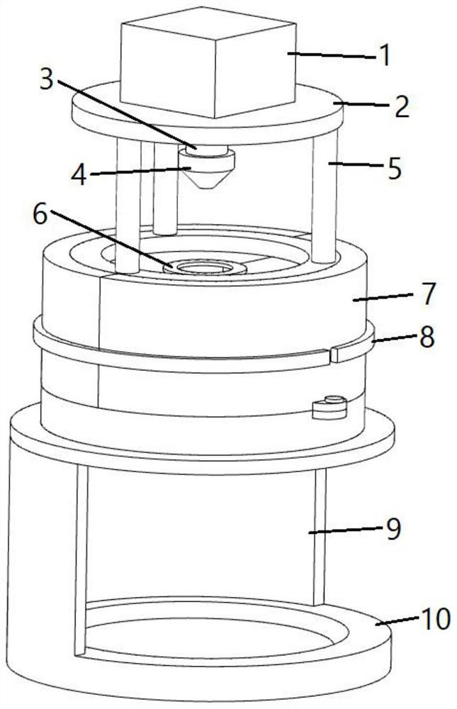
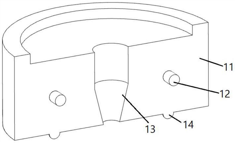
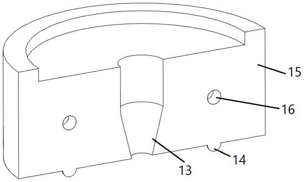
The invention discloses a nano hard alloy micro-drill bar production system, and relates to the technical field of mold machining. An oil cylinder is arranged at the upper end of a top bracket, and a punching head is fixed on an output shaft at the lower end of the oil cylinder; supporting columns are arranged on the periphery of the lower side of the top support, and a clamping plate is fixed to the lower ends of the supporting columns; a first die plate is arranged on the lower side of the clamping plate, a second die plate is fixed on the lower side of the first die plate, and a storage device is arranged on the lower side of the second die plate; a material accommodating cavity and a mold cavity which are communicated with each other are formed in the first die plate and the second die plate respectively; the first die plate is provided with a left die and a right die, and the cross sections of the left die and the right die are semicircular; a heating device is arranged outside the lower end of the material accommodating cavity, and a cooling device is arranged outside the cavity; and the storage device is provided with a base, a supporting plate is arranged on the upper side of the base, and a placing groove is formed in the middle of the upper side of the base. The die plates can be prevented from being blocked, meanwhile, disassembly and cleaning are convenient, the forming effect of the die is guaranteed, and the product quality is improved.

Description

technical field [0001] The disclosure of the invention relates to the technical field of mold processing, in particular to a production system for nano-hard alloy micro-drilling rods. Background technique [0002] Mold processing refers to the processing of forming and billet tools, and also includes shearing dies and die-cutting dies. Usually, the mold consists of two parts, the upper mold and the lower mold. The steel plate is placed between the upper and lower molds, and the material is formed under the action of the press. When the press is opened, the workpiece determined by the shape of the mold is obtained or the corresponding waste is removed. [0003] Existing molds for processing alloy rods, when in use, the rods in the cavity cannot fall off automatically due to the large friction between itself and the inner wall of the mold cavity; The material for making the bar alloy has a large frictional force with the lower end of the loading cavity, which is likely to ca...

Claims


Application Information

Patent Timeline
IPC IPC(8): B21C23/18B21C23/21B21C25/02B21C29/00
CPCB21C23/183B21C23/212B21C25/02B21C29/003
Inventor 孙浩斌颜练武张华李昌业司守佶王焕涛
Owner 蓬莱市超硬复合材料有限公司
Learn More