
Junction box grabbing and assembling mechanism and photovoltaic bus bar assembling and bending device

A technology of assembling mechanism and junction box, which is applied to photovoltaic modules, feeding devices, positioning devices, etc., can solve problems such as affecting use, and achieve the effects of preventing wrong bending, tight structural coordination, and preventing center of gravity from shifting.

Pending Publication Date: 2021-06-25
CHUZHOU HONGZHAN INTELLIGENT TECH CO LTD
View PDF5 Cites 3 Cited by
  • Summary
  • Abstract
  • Description
  • Claims
  • Application Information

AI Technical Summary

Problems solved by technology

[0002] Photovoltaic junction box is a connection device between the solar cell square array composed of solar cell components and the solar charging control device. Its main function is to connect and protect solar photovoltaic components, connect the power generated by solar cells with external lines, and conduct photovoltaic current generated by components, usually including housings and wires, such as Image 6 As shown in the junction box, there are two long slots in the center, and the Figure 7 After the bus bar on the photovoltaic panel shown is inserted, the bus bar is bent to both sides. To achieve the above method, it can only be done manually. The design of the mechanical structure often interferes with each other, which affects the use.

Method used


Image

  • Junction box grabbing and assembling mechanism and photovoltaic bus bar assembling and bending device
  • Junction box grabbing and assembling mechanism and photovoltaic bus bar assembling and bending device
  • Junction box grabbing and assembling mechanism and photovoltaic bus bar assembling and bending device

Examples


Embodiment Construction

[0022] The following will clearly and completely describe the technical solutions in the embodiments of the present invention with reference to the drawings in the embodiments of the present invention.

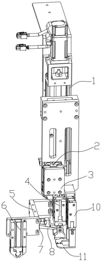
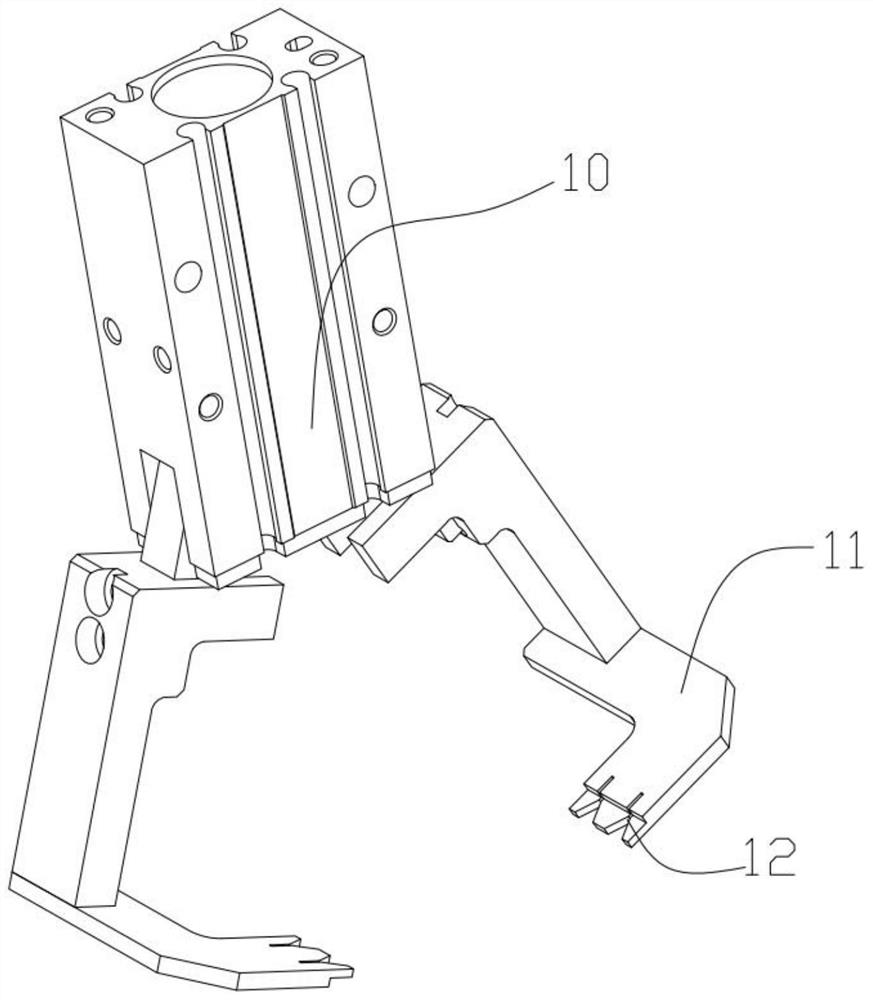
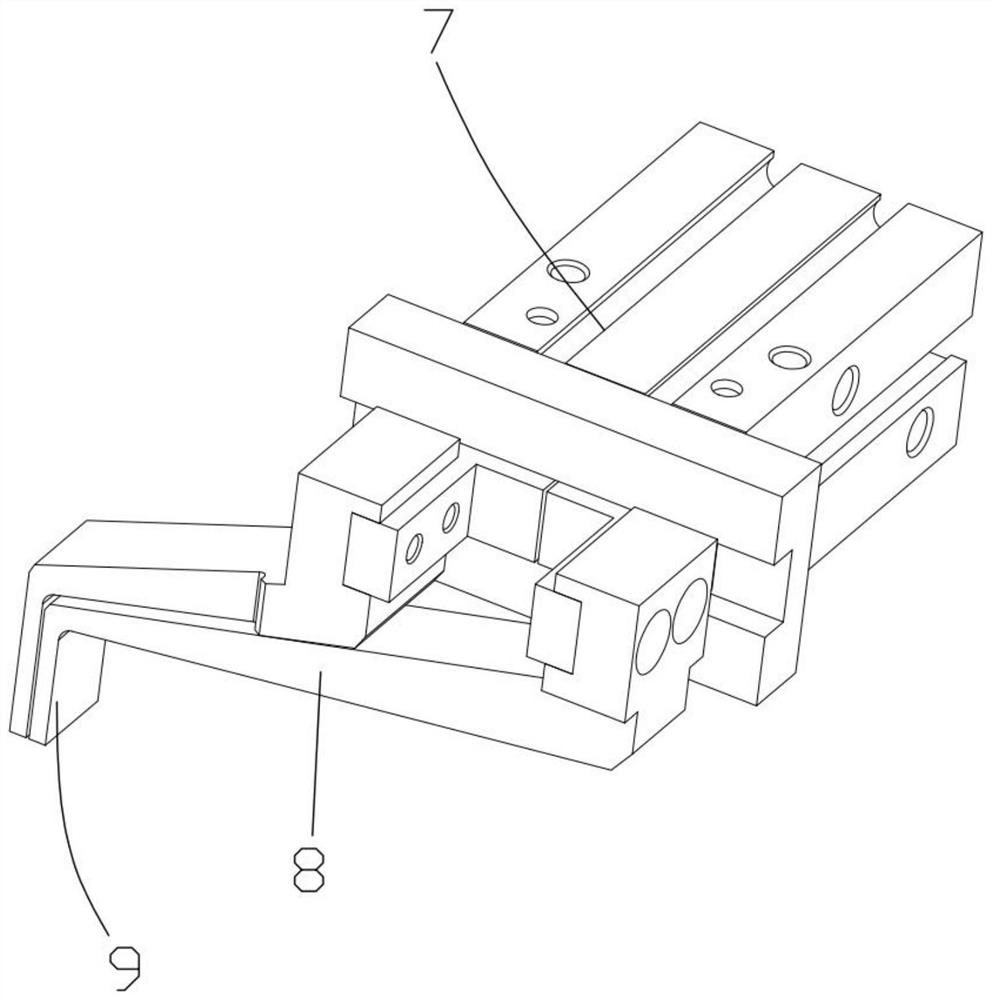
[0023] Such as Figure 1-Figure 3 As shown, the present invention proposes a junction box grasping and assembling mechanism, including a lifting mechanism 1, which is provided with a downward pressure cylinder 2, and the lifting mechanism 1 is a screw module, which is used to lower the entire grasping Up and down movement when taking the product, the output end of the press-down cylinder 2 is connected to a mounting plate 3, the mounting plate 3 is provided with a first jaw cylinder 4, and a bus bar is provided on the side of the first jaw cylinder 4 The positioning mechanism, the bus bar positioning mechanism is fixedly connected with the lifting mechanism 1, the lifting mechanism 1 is provided with a fixed plate, and the bus bar positioning mechanism is connected with the fi...


PUM


Abstract

The invention provides a junction box grabbing and assembling mechanism and a photovoltaic bus bar assembling and bending device. A lifting mechanism is included, a downward pressing air cylinder is arranged on the lifting mechanism, and the output end of the downward pressing air cylinder is connected with a mounting plate. First clamping jaw air cylinders are arranged on the mounting plate, and a bus bar positioning mechanism is arranged on the side edge of each first clamping jaw air cylinder. The bus bar positioning mechanism is fixedly connected with the lifting mechanism. An extension plate is further arranged on the mounting plate, and a second clamping jaw air cylinder is arranged at the upper end of the extension plate. A bending air cylinder is further included, the output end of the bending air cylinder is provided with a bending arm, and the bending arm extends between the first clamping jaw air cylinders. Through reasonable structural configuration of the mechanism, a junction box can be stably grabbed, and the situation that the gravity center of the junction box shifts, and assembling is affected is prevented; and meanwhile, when the junction box is inserted with the bus bar after being grabbed, the bus bar can be effectively prevented from being bent by mistake. And after being inserted into the junction box, the bus bar can be bent and pressed into the junction box, and the structure can be tightly matched.

Description

technical field [0001] The invention relates to the field of photovoltaic assembly equipment, in particular to a junction box grasping and assembling mechanism and a photovoltaic bus bar assembling and bending mechanism. Background technique [0002] Photovoltaic junction box is a connection device between the solar cell square array composed of solar cell components and the solar charging control device. Its main function is to connect and protect solar photovoltaic components, connect the power generated by solar cells with external lines, and conduct photovoltaic current generated by components, usually including housings and wires, such as Figure 6 As shown in the junction box, there are two long slots in the center, and the Figure 7 After the bus bar on the photovoltaic panel shown is inserted, the bus bar is bent to both sides. To achieve the above method, generally only manual operation is possible. The design of the mechanical structure often interferes with each o...

Claims


Application Information

Patent Timeline
Patent Type & Authority Applications(China)
IPC IPC(8): B21D7/06B21D43/00H02S40/34
CPCB21D7/06B21D43/003H02S40/34Y02E10/50
Inventor 李剑峰
Owner CHUZHOU HONGZHAN INTELLIGENT TECH CO LTD
Learn More