Coding equipment for medical packaging bottles

A technology for packaging bottles and medical use, which is applied in the field of coding equipment for medical pharmaceutical packaging bottles. It can solve the problems of simple and convenient operation and maintenance, unclear printing fonts, and unreasonable use costs, so as to save time for manual collection. , Precise feeding operation, clear printing effect

Active Publication Date: 2022-05-27
无锡西奇智能科技有限公司
View PDF8 Cites 0 Cited by
  • Summary
  • Abstract
  • Description
  • Claims
  • Application Information

AI Technical Summary

Problems solved by technology

[0004] In order to overcome the disadvantages of poor printing effect, unclear printing fonts, simple and convenient operation and maintenance, and unreasonable cost of use, the technical problem to be solved is: to provide a kind of inkjet printer with good printing effect, clear fonts, stable and reliable performance, and easy operation. It should be simple and convenient to maintain and maintain, and the cost of use should be reasonable. Medical drug packaging bottle coding equipment

Method used


Image

  • Coding equipment for medical packaging bottles
  • Coding equipment for medical packaging bottles
  • Coding equipment for medical packaging bottles

Examples


Embodiment 1

[0059] A medical drug packaging bottle coding equipment, such as figure 1 As shown, it includes a base 1, a support plate 2, a work frame 3, a push mechanism 4 and a rotation mechanism 5. The back of the base 1 is provided with a support plate 2, the base 1 is provided with a work frame 3, and the support plate 2 is provided with a push mechanism 4. A rotating mechanism 5 is arranged between the support plate 2 and the work frame 3 .

[0060] When people need to spray code on the material, they put the material on the work frame 3, then start the push mechanism 4, and the push mechanism 4 drives the rotating mechanism 5 to move, so that the material is transported by the rotating mechanism 5, and then the material is sprayed. After the operation is completed, the push mechanism 4 is closed, and the rotation mechanism 5 stops moving.

Embodiment 2

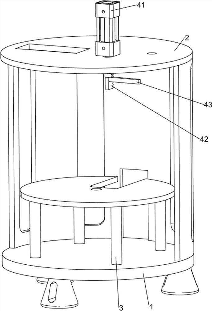
[0062] On the basis of Example 1, as Figure 2 to Figure 3 As shown, the pushing mechanism 4 includes a cylinder 41, a rack 42 and a first connecting rod 43, a cylinder 41 is provided on the top of the support plate 2, a rack 42 is provided on the cylinder 41, and a first connecting rod is provided on the right front of the rack 42 43.

[0063] The rotating mechanism 5 includes a rotating table 51 , a first rotating shaft 52 , a second rotating shaft 53 , a bevel gear set 54 and a one-way gear 55 . The table 51, the rotary table 51 is in contact with the work frame 3, the right part of the support plate 2 is rotatably connected with a second rotating shaft 53, the left part of the second rotating shaft 53 is provided with a one-way gear 55, and the one-way gear 55 meshes with the rack 42, A bevel gear set 54 is provided between the left part of the second rotating shaft 53 and the upper part of the first rotating shaft 52 .

[0064]When people need to code the material, plac...

Embodiment 3

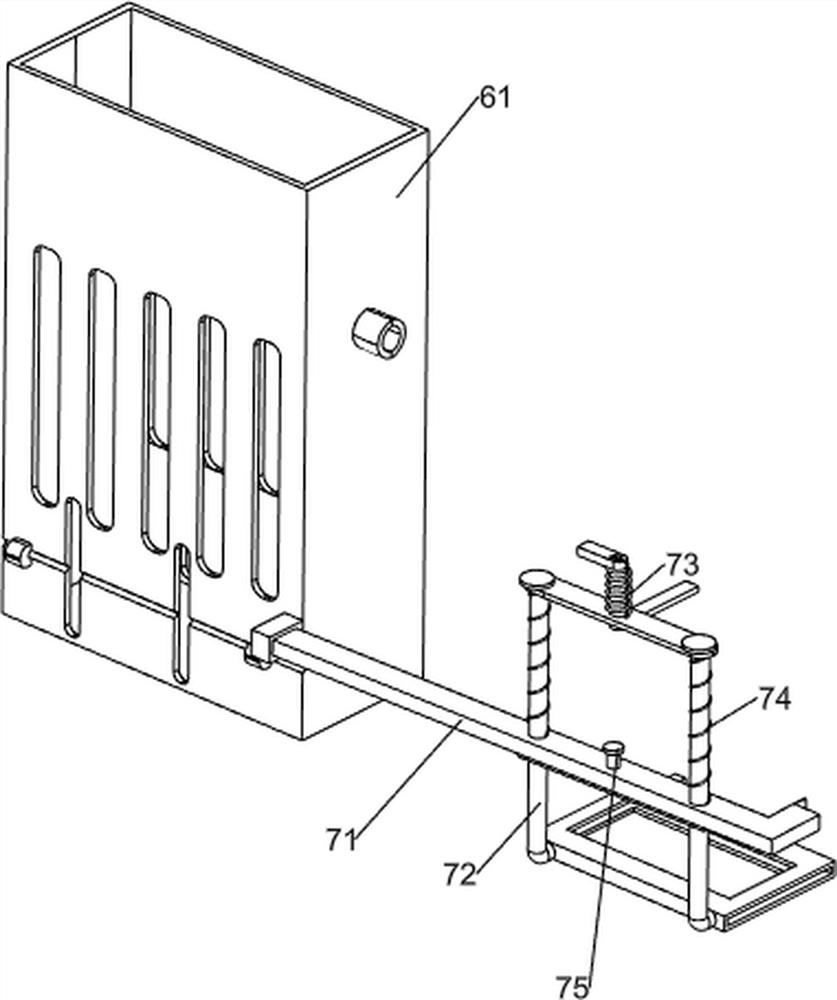
[0066] On the basis of Example 2, as Figure 4 to Figure 9 As shown, it also includes a feeding mechanism 6. The feeding mechanism 6 includes a feeding box 61, an extrusion block 62, a first rotating rod 63, a second connecting rod 64, a second rotating rod 65, and a first compression spring 66. , the first clamping block 67 and the ejector rod 68, there are four extrusion blocks 62 evenly distributed on the rotary table 51, the upper left part of the support plate 2 is provided with a feeding box 61, and the front side of the lower part of the feeding box 61 is rotatably connected with a second A rotating rod 63, a second rotating rod 65 is rotatably connected to the rear side of the lower part of the feeding box 61, and first clamping blocks 67 are provided on the left and right sides of the first rotating rod 63 and the second rotating rod 65. A top rod 68 is slidably connected to the lower side of the lower part. The top rod 68 is slidably connected to the middle of the fi...


PUM


Abstract

The invention relates to a coding device, in particular to a coding device for medical medicine packaging bottles. The technical problem to be solved is: to provide a medical drug packaging bottle coding equipment with good coding effect, clear font, stable and reliable performance, simple and convenient operation and maintenance, and reasonable cost of use. The technical scheme of the present invention is: a coding equipment for medical packaging bottles, including: a support plate, a support plate is provided on a part of the base; a work frame, a work frame is provided on the base; A pushing mechanism; a rotating mechanism, a rotating mechanism is arranged between the support plate and the working frame. Through the function of the collection mechanism, the printed materials can be collected, which saves the time of manual collection; through the cooperation of the rotating mechanism and the feeding mechanism, the interval transportation of the materials can be realized.

Description

technical field [0001] The invention relates to a coding device, in particular to a coding device for medical medicine packaging bottles. Background technique [0002] Coding refers to the process of using inkjet printer to print logos on products, such as production date, shelf life, batch number, corporate logo, etc., which is conducive to product identification, can track and record products, and can better prevent counterfeiting, especially for For medical supplies, coding plays a big role. [0003] However, the printing effect of many inkjet printers is not good, the printing fonts are not clear enough, the operation and maintenance are not simple and convenient, and the use cost is not reasonable. It is convenient and cost-effective to use the coding equipment for medical drug packaging bottles. SUMMARY OF THE INVENTION [0004] In order to overcome the shortcomings of poor printing effect, unclear fonts, simple and convenient operation and maintenance, and unreaso...

Claims


Application Information

Patent Timeline
Patent Type & Authority Patents(China)
IPC IPC(8): B41J3/407B41J29/393B41J11/00B65G47/80
CPCB41J3/4073B41J29/393B41J11/00B65G47/80B65G2201/0244
Inventor 李玉康
Owner 无锡西奇智能科技有限公司
Why Eureka
Try Eureka