Underwater outer limb and application thereof

A technology of limbs and outer side walls, applied in the directions of underwater ships, underwater operation equipment, special-purpose ships, etc., can solve the problems of reducing the propulsion efficiency of the propeller, poor hydrodynamic performance, and hindering the inflow of the propeller.

Active Publication Date: 2021-06-25
SOUTH UNIVERSITY OF SCIENCE AND TECHNOLOGY OF CHINA
View PDF10 Cites 0 Cited by
  • Summary
  • Abstract
  • Description
  • Claims
  • Application Information

AI Technical Summary

Problems solved by technology

The main problem is that the propeller with redundant degrees of freedom not only leads to its complex shape and structure, poor hydrodynamic performance, poor slewing performance, etc., but also the narrow rack space and dense equipment hinder the inflow of the propeller, which will also Further reduce the propulsion efficiency of the propeller
This has caused limitations in the design, manufacture, installation and use of underwater robots

Method used


Image

  • Underwater outer limb and application thereof
  • Underwater outer limb and application thereof
  • Underwater outer limb and application thereof

Examples


Embodiment 1

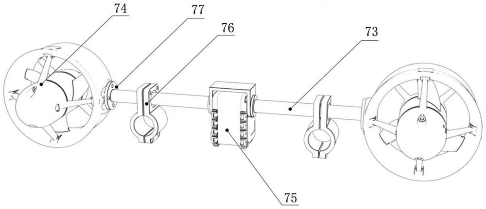
[0052] Such as figure 1 As shown, the underwater extremity also includes a connection assembly, and the connection assembly includes a positioning rod 73 and a hoop member 76. The output end of the driver 75 is connected to one end of the positioning rod 73, and the other end of the positioning rod 73 is connected to the outer side wall of the propeller 74. Connection; the upper side of the hoop member 76 is provided with a through hole, and the positioning rod 73 is rotatably passed through the through hole.

[0053] In this embodiment, a driver 75 is used to drive the positioning rod 73 to rotate, thereby driving the propeller 74 to rotate, and the hoop member 76 plays an auxiliary fixing role. The through hole of the hoop member 76 can be provided with a bearing, and the positioning rod 73 is installed on the bearing. on the inner ring.

Embodiment 2

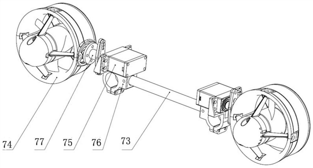
[0055] Such as figure 2 As shown, the difference from Embodiment 1 is that there are two drivers: the connecting assembly includes a positioning rod 73 and a hoop member 76, and the left and right ends of the positioning rod 73 are respectively connected with a hoop member 76, and one side of the hoop member 76 is A driver 75 is installed, and the output end of the driver 75 is connected to the outer side wall of the pusher 74 through the second connecting piece 77 . In a specific embodiment, the connecting member 77 adopts a connecting flange.

[0056] The hoop piece plays a fixing role and is used to fix the driver 75, and the positioning rod 73 is connected to the drivers 75 arranged symmetrically on the left and right sides. The left and right drivers 75 are respectively used to independently control the propulsion direction of the propeller 74. The positioning rod 73 is used to connect the two drivers 75 on the one hand, and keeps the axes of the output shafts of the dr...

Embodiment 3

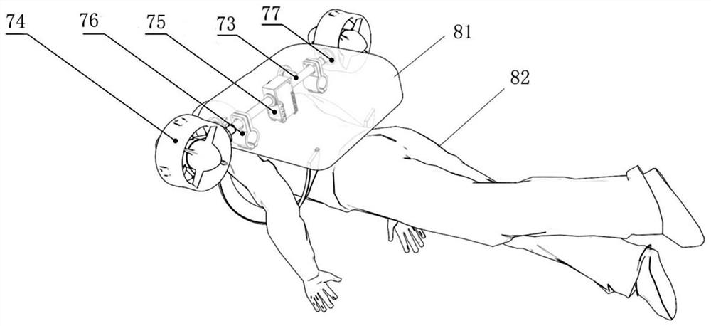
[0058] Such as image 3 As shown, the underwater extremities of the present invention can be applied to underwater driving backpacks:

[0059] The driver 75 is fixed in the underwater driving backpack 81, and the left and right sides of the underwater driving backpack 81 are respectively provided with propellers 74, and the output end of the driver 75 is connected with the outer side wall of the propeller 74.

[0060] After the diving operator 82 is equipped with the underwater driving backpack 81, he can adjust the propulsion angle of the propeller 75 through the driver 75 to perform multi-degree-of-freedom movements.


PUM


Abstract

The invention discloses an underwater outer limb and application thereof, and belongs to the technical field of ocean engineering. The underwater outer limb comprises a driver and a propeller, and the output end of the driver is connected with the outer side wall of the propeller. The propeller is used for providing power or auxiliary power, and the driver is used for adjusting the axis angle of the propeller, so that the propelling direction of the propeller is adjusted, multi-angle power or auxiliary power is provided, and underwater multi-mode movement or operation is achieved; the underwater outer limb can be applied to underwater driving knapsacks and underwater robots.

Description

technical field [0001] The invention relates to the technical field of marine engineering, in particular to an underwater extremity and its application. Background technique [0002] With the deepening of marine scientific research and the development of marine energy resources around the world, underwater robot technology has developed rapidly and has been widely used in the fields of marine environment monitoring, marine resource survey and development, and scientific investigation. Among them, the shallow kelp (through the layer) with a water depth of 0-200 meters is full of sunlight, and the types and quantities of various organisms far exceed those in other depths. The marine scientific investigation and resource development of shallow kelp usually requires the help of marine technology equipment, such as underwater robots capable of underwater operations. [0003] At present, in order to meet the minimum mobility requirements of underwater robots, underwater robots ne...

Claims


Application Information

Patent Timeline
Patent Type & Authority Applications(China)
IPC IPC(8): B63C11/02B63G8/16B62D57/032
CPCB63C11/02B63G8/16B62D57/032
Inventor 宋超阳冯世豪顾宇平郭宇芹陈铭栋
Owner SOUTH UNIVERSITY OF SCIENCE AND TECHNOLOGY OF CHINA
Why Eureka
Try Eureka