
Vector ducted tail rotor high-speed helicopter

A helicopter, high-speed technology, applied in the direction of rotorcraft, motor vehicles, aircraft, etc., can solve the problems of multi-coupling control channels, large pressure difference resistance, difficult to control, etc., to reduce aerodynamic noise, stable and uniform airflow, and improve aerodynamic efficiency Effect

Pending Publication Date: 2021-06-25
BEIHANG UNIV
View PDF8 Cites 5 Cited by
  • Summary
  • Abstract
  • Description
  • Claims
  • Application Information

AI Technical Summary

Problems solved by technology

However, for the combination structure scheme of lift wing and vector tail rotor, the existing vector tail rotor schemes are aerodynamic rudder surface vector, that is, the ducted fan is fixed, and the adjustable aerodynamic rudder surface is installed at the tail of the ducted fan. Vector propulsion control has more control channels and stronger coupling. Compared with the conventional tail rotor, the stability is poorer and it is difficult to control. At the same time, because the rudder surface is behind the ducted fan, the pressure difference resistance is also relatively large.

Method used


Image

  • Vector ducted tail rotor high-speed helicopter
  • Vector ducted tail rotor high-speed helicopter
  • Vector ducted tail rotor high-speed helicopter

Examples


Embodiment Construction

[0022] The present invention will be further described below in conjunction with the accompanying drawings and examples. It should be understood that the following examples are intended to facilitate the understanding of the present invention, and have no limiting effect on it.

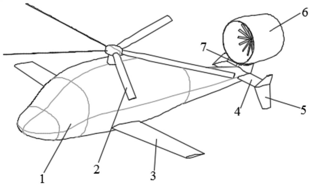
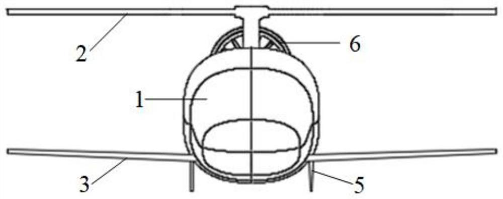
[0023] like Figure 1-5 As shown, the composite high-speed helicopter that adopts the ducted rotatable vector tail rotor provided by this embodiment includes a fuselage 1, a main rotor 2, a lift wing 3, a horizontal tail 4, a vertical tail 5, a ducted fan 6 and Duct rotating shaft 7. Wherein, the main rotor 2 is installed directly above the fuselage 1, and the lift wing 3 is symmetrically installed on the lower half of both sides of the fuselage 1, so as to weaken the unfavorable aerodynamic interference effect between the main rotor 2 and the lift wing 3. The horizontal stabilizer 4 is rigidly connected to both sides of the tail of the fuselage 1 symmetrically, and the vertical stabilizer 5 is insta...


PUM


Abstract

The invention belongs to the field of aerodynamic layout design of aircrafts, and particularly relates to a vector ducted tail rotor high-speed helicopter which comprises a fuselage, a main rotor, lift wings, a horizontal empennage, a vertical empennage and a ducted fan, and an air inlet of the ducted fan faces the fuselage, is rotatably connected with the upper portion of the tail of the fuselage and can horizontally rotate above the tail of the fuselage; when the helicopter flies forwards at a high speed, an angle alpha is formed between the central axis of the ducted fan and the central axis of the fuselage and is larger than or equal to 0 degree and smaller than 90 degrees, and alpha is equal to 90 degrees during hovering and low-speed flying. Vector control of tail thrust is achieved by horizontally rotating the whole ducted fan, the defect of a common ducted tail rotor in control efficiency is overcome, control efficiency and action efficiency are improved, and the flight speed is greatly increased. In addition, the number of control channels of the vector ducted tail rotor system is relatively small, and the operation steps of a pilot are simplified; and as the tail of the ducted fan is not provided with a pneumatic control surface, airflow in a wake flow area is more stable and uniform, and flight is safer.

Description

technical field [0001] The invention belongs to the field of aircraft aerodynamic layout design, in particular to a high-speed helicopter with a vector ducted tail rotor that adopts a ducted rotatable vector tail rotor system and is equipped with lift wings. Background technique [0002] High-tech local wars under the modern new military transformation environment put forward higher requirements on the performance of helicopters, and there is an urgent need for a high-speed helicopter that can significantly improve the military's combat, rescue and transportation capabilities. When the helicopter is flying forward at high speed, the speed at the tip of the forward blade (that is, the tangential speed of the blade is in the same direction as the forward flight speed of the helicopter) is the superposition of the tangential speed of the rotor and the forward flight speed of the helicopter. The speed at the tip is the difference between the two, so there will be a large dynamic...

Claims


Application Information

Patent Timeline
Patent Type & Authority Applications(China)
IPC IPC(8): B64C27/26B64C27/82
CPCB64C27/26B64C27/82B64C2027/8254B64C2027/8281B64C2027/829
Inventor 蒋崇文何新李志豪许晨豪高振勋李椿萱
Owner BEIHANG UNIV
Learn More