Auxiliary power device and exhaust control method of auxiliary power device

A technology of auxiliary power unit and power, which is applied in the exhaust control of auxiliary power unit and the field of auxiliary power unit, and can solve the problems of large fuel consumption and poor economy of auxiliary power unit

Active Publication Date: 2021-06-25
AECC HUNAN AVIATION POWERPLANT RES INST
View PDF8 Cites 1 Cited by
  • Summary
  • Abstract
  • Description
  • Claims
  • Application Information

AI Technical Summary

Problems solved by technology

[0004] The auxiliary power unit provided by the present invention solves the technical problem that the load compressor is rotating at high speed in any working state of the existing auxiliary power unit, resulting in large fuel consumption and poor economic efficiency of the auxiliary power unit

Method used


Image

  • Auxiliary power device and exhaust control method of auxiliary power device
  • Auxiliary power device and exhaust control method of auxiliary power device
  • Auxiliary power device and exhaust control method of auxiliary power device

Examples


Embodiment Construction

[0027] The embodiments of the present invention will be described in detail below with reference to the accompanying drawings, but the present invention can be implemented in various ways defined and covered below.

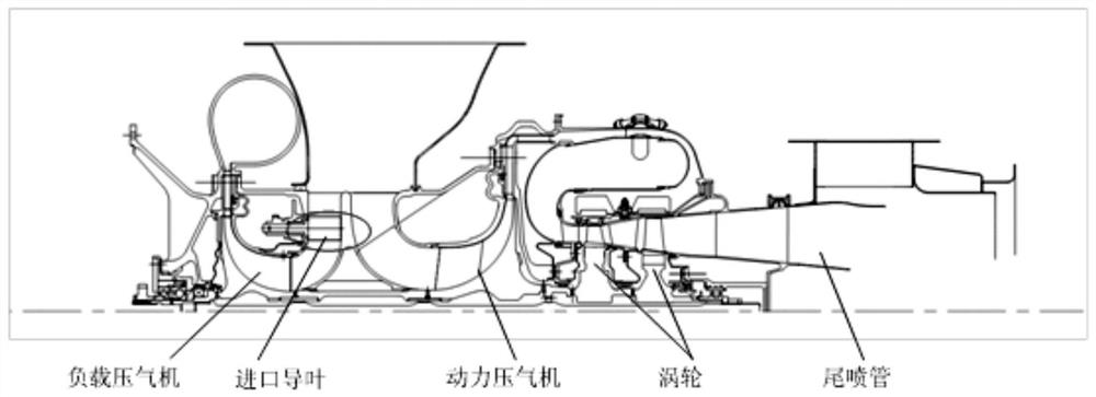
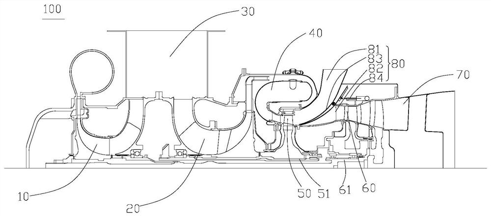
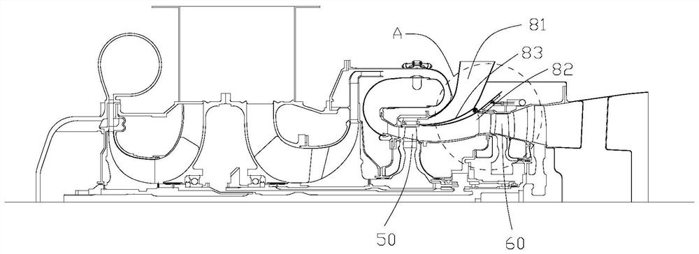
[0028] figure 1 is a structural schematic diagram of an auxiliary power unit in the prior art; figure 2 is a schematic structural diagram of the first state of the auxiliary power unit in the preferred embodiment of the present invention; image 3 is a schematic structural diagram of the second state of the auxiliary power unit in the preferred embodiment of the present invention; Figure 4 yes image 3 The magnified image at A in the middle; Figure 5 It is a schematic diagram of the cooperation between the sliding block and the sliding rail of the auxiliary power unit in the preferred embodiment of the present invention.

[0029] Such as figure 2 with image 3As shown, the auxiliary power unit 100 of this embodiment includes a load compressor 10 and a po...


PUM


Abstract

The invention discloses an auxiliary power device and an exhaust control method of the auxiliary power device. The device comprises a load gas compressor, a power gas compressor, a combustion chamber located at an airflow outlet of the power gas compressor, a gas turbine located at the downstream of the combustion chamber, a free turbine located at the downstream of the gas turbine and an exhaust nozzle located at the downstream of the free turbine and used for discharging high-temperature gas output by the free turbine. An exhaust adjusting mechanism is arranged between the free turbine and the gas turbine and used for guiding high-temperature gas output by the gas turbine into the free turbine so as to drive the free turbine to rotate or used for guiding the high-temperature gas output by the gas turbine out of the free turbine from the gas inlet side of the free turbine. According to the auxiliary power device, normal functions of air entraining, power generation and the like of a load air compressor of an existing auxiliary power device can be achieved, the load air compressor does not work in the non-air-entraining state of the load air compressor, then power consumption of the load air compressor is reduced, and economic benefits are good.

Description

technical field [0001] The invention relates to the technical field of gas turbine engines, in particular, to an auxiliary power device. The invention also relates to an exhaust gas control method of an auxiliary power unit. Background technique [0002] Such as figure 1 As shown, the auxiliary power unit (APU) often adopts the bleed air of the load compressor, and the intake air volume entering the load compressor is controlled through the inlet guide vane at the air inlet of the load compressor. When bleed air is required, the inlet guide vane is opened, and the airflow in the intake casing enters the load compressor, which is compressed and sent to the aircraft's environmental control system and main engine starting system; when bleed air is not needed, the inlet guide vane is closed , let as little airflow as possible enter the load compressor, reduce the work of the load compressor, thereby reducing useless fuel consumption. [0003] At present, whether it is a singl...

Claims


Application Information

Patent Timeline
Patent Type & Authority Applications(China)
IPC IPC(8): B64D41/00B64D33/04
CPCB64D41/007B64D33/04
Inventor 李春黄攀龚艳红刘雨澄王赛
Owner AECC HUNAN AVIATION POWERPLANT RES INST
Why Eureka
Try Eureka