Grooving reinforcing structure for ultra-deep underground diaphragm wall in coastal reclamation area and construction method thereof

An underground diaphragm wall and reinforcement structure technology, which is applied in infrastructure engineering, sheet pile walls, buildings, etc. Water-stopping performance, good reinforcement and water-stopping effect, and the effect of preventing the collapse of the groove wall

Active Publication Date: 2021-06-25
CHINA CONSTR FIRST BUILDING GRP CORP LTD +1
View PDF9 Cites 1 Cited by
  • Summary
  • Abstract
  • Description
  • Claims
  • Application Information

AI Technical Summary

Problems solved by technology

[0004] The purpose of the present invention is to provide an ultra-deep underground diaphragm wall trough reinforcement structure and construction method in the seaside push-fill area, to solve the problem that the underground diaphragm wall groove wall is prone to collapse due to the high groundwater level and unstable soil in the sea-side push-fill area It is also necessary to solve the technical problems of the underground diaphragm wall in the coastal reclamation area when the reinforcement depth of the underground diaphragm wall exceeds 30m. Due to the high water and soil pressure, the reinforcement effect of the existing single reinforcement method is poor and the groove wall is more likely to collapse, especially there are still groove walls. Stable, difficult to form the reinforced body, difficult to meet the technical problems of the reinforcement effect

Method used


Image

  • Grooving reinforcing structure for ultra-deep underground diaphragm wall in coastal reclamation area and construction method thereof
  • Grooving reinforcing structure for ultra-deep underground diaphragm wall in coastal reclamation area and construction method thereof
  • Grooving reinforcing structure for ultra-deep underground diaphragm wall in coastal reclamation area and construction method thereof

Examples


Embodiment Construction

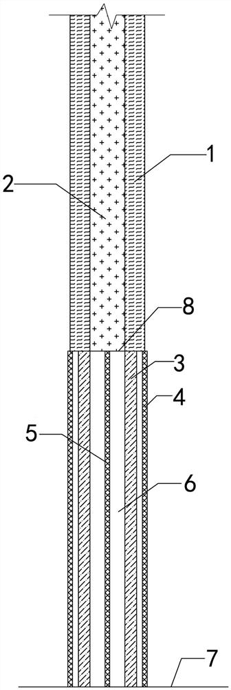
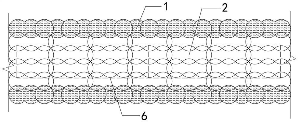
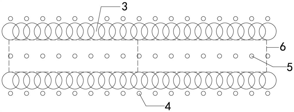
[0038] Examples see Figure 1-3 As shown, an ultra-deep underground diaphragm wall trough reinforcement structure in the seaside push fill area is formed in the groove section of the underground diaphragm wall 6 and in the soil around the groove section, and includes a combined reinforcement structure. The combined reinforcement structure includes upper and lower The upper reinforcement structure and the lower reinforcement structure are connected as a whole, with a fixed height as the dividing line. In this embodiment, the height dividing line 8 between the upper reinforcement structure and the lower reinforcement structure in the combined reinforcement structure is 30m.

[0039] The upper reinforcement structure includes a three-axis stirring pile 1 outside the tank and a three-axis stirring pile 2 inside the tank, and the reinforcement depth of the upper reinforcement structure ranges from the ground to 30m underground. The three-axis stirring pile 1 outside the tank and t...


PUM


Abstract

The invention provides a grooving reinforcing structure for an ultra-deep underground diaphragm wall in a coastal reclamation area and a construction method thereof. The structure comprises an upper reinforcing structure within the range of 30m and a lower reinforcing structure within the range of 30m or below. The upper reinforcing structure is reinforced and formed through a three-axis mixing pile, the quality is good, and a good reinforcing and water stopping effect is achieved. Within the range of 30m or below, due to the fact that the water and soil pressure of the coastal reclamation area is large, the reinforcing effect cannot be guaranteed through a single groove wall reinforcing manner, a high-pressure jet grouting pile is adopted for reinforcing firstly, and then the defects possibly existing in the high-pressure jet grouting pile are overcome through sleeve valve grouting. The grooving reinforcing structure combines the advantages of the three-axis mixing pile, the high-pressure jet grouting pile and sleeve valve pipe grouting, a good groove wall reinforcing effect can be achieved during underground diaphragm wall construction, the grooving reinforcing structure is particularly suitable for grooving reinforcing of the ultra-deep underground diaphragm wall in the coastal reclamation area, and the groove wall reinforcing method is safe, effective, economical and reasonable.

Description

technical field [0001] The invention belongs to the field of groove wall reinforcement, in particular to a groove-forming reinforcement and a construction method of an ultra-deep underground continuous wall in a seaside push-fill area. Background technique [0002] With the continuous development of my country's construction projects, various deep and large foundation pits such as foundation pits with a depth of 20 to 30 meters have emerged in large numbers. For deep and large foundation pits, the underground diaphragm wall has become a very important form of support. Due to the lack of the "round arch effect" similar to the supporting piles during the construction of the underground diaphragm wall, the stability of the trench is relatively poor. Therefore, when the geological conditions are poor, the trench wall is often reinforced before the construction of the diaphragm wall. Groove construction. [0003] According to the current underground diaphragm wall construction ...

Claims


Application Information

Patent Timeline
Patent Type & Authority Applications(China)
IPC IPC(8): E02D17/08E02D5/46E02D15/04
CPCE02D17/08E02D5/46E02D15/04
Inventor 孟庆礼崔玉音邓美龙程培春李喆刘大硕赵艳刘宴伟费立敏张宝
Owner CHINA CONSTR FIRST BUILDING GRP CORP LTD
Why Eureka
Try Eureka