Oil-gas separation structure of engine

A separation structure and engine technology, applied in the direction of engine components, machines/engines, mechanical equipment, etc., can solve the problems of chaotic flow of oil and gas mixture, reduce the effect of oil and gas separation in the oil and gas separation chamber, and achieve high oil and gas separation efficiency and improve oil and gas separation efficiency. , good separation effect

Pending Publication Date: 2021-06-25
ZHEJIANG QIANJIANG MOTORCYCLE
View PDF1 Cites 0 Cited by
  • Summary
  • Abstract
  • Description
  • Claims
  • Application Information

AI Technical Summary

Problems solved by technology

However, in this kind of structural oil-gas separation device, the oil outlets of oil return hole 1 and oil return hole 2 are located at the upper part of the inner cavity of the gearbox, and there is an oil-air mixture at the upper part of the inner cavity of the gearbox, that is, the oil-air mixture exists through the return The problem that the oil hole 1 and the oil return hole 2 enter the oil-gas separation chamber, which leads to the confusion of the flow of the oil-gas mixture in the oil-gas separation chamber and reduces the oil-gas separation effect of the oil-gas separation chamber

Method used


Image

  • Oil-gas separation structure of engine
  • Oil-gas separation structure of engine
  • Oil-gas separation structure of engine

Examples


Embodiment Construction

[0024] The following are specific embodiments of the present invention and in conjunction with the accompanying drawings, further describe the technical solution of the present invention, but the present invention is not limited to these embodiments.

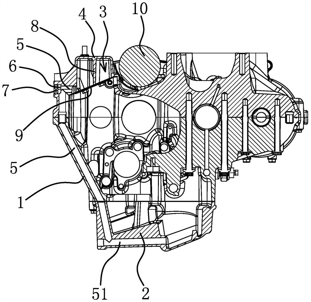
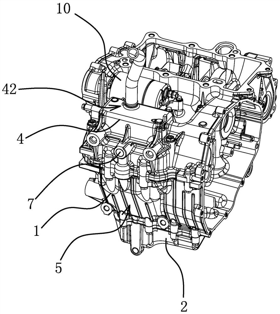
[0025] Such as figure 1 , figure 2 As shown, the engine includes a casing 1 , an oil pan 2 , an oil-gas separation structure and an air filter 10 , and the oil pan 2 is arranged at the bottom of the casing 1 . The oil-gas separation structure includes a separation case 4, an oil outlet channel 5, a partition 8 and a bottom plate 9, and the box body 1, the separation case 4 and the partition 8 are an integral structure.

[0026] The separation case 4 protrudes from the case body 1 , the air filter 10 is fixedly connected to the case body 1 , and the separation case 4 and the air filter 10 are adjacently arranged. The bottom of the separation case 4 has an opening connecting the cavity of the separation case 4 and the cavity of...


PUM


Abstract

The invention provides an oil-gas separation structure of an engine, and belongs to the technical field of engines. The oil-gas separation structure solves the problem that an oil-gas mixture reversely enters a separation channel from an oil outlet channel in an existing oil-gas separation structure. The engine comprises a box body, wherein an oil pan is arranged at the bottom of the box body; the oil-gas separation structure involves a separation shell and an oil outlet channel, wherein the separation shell is arranged on the box body in a protruding mode, a separation channel is arranged inside the separation shell, and the oil outlet channel is arranged in the box wall of the box body; and the oil inlet end of the oil outlet channel communicates with the separation channel, and the oil outlet end of the oil outlet channel communicates with an inner cavity of the oil pan. The oil-gas separation structure of the engine prevents an oil-gas mixture from reversely entering the separation channel from the oil outlet channel.

Description

technical field [0001] The invention belongs to the technical field of engines and relates to an engine oil-gas separation structure. Background technique [0002] When the engine is working, part of the combustible fuel-air mixture containing oil and exhaust gas will enter the tank, thereby increasing the pressure inside the tank and threatening the stability of the engine system. Separation, the separated gas re-enters the cylinder for combustion or is discharged, and the separated oil returns to the oil pan for reuse. [0003] The existing engine oil-gas separation structure, for example, Chinese patent literature discloses an oil-gas separation device for motorcycle gearboxes [application number: 202010058413.0; application publication number: CN111156067A], which includes an oil-gas separation device installed on the gearbox case Chamber, air inlet, air outlet, and a labyrinth separation structure between the air inlet and the air outlet. The air inlet is used to conne...

Claims


Application Information

Patent Timeline
IPC IPC(8): F01M13/04
CPCF01M13/04F01M2013/0433
Inventor 张立成邓定红李良周鹏博莫康鑫
Owner ZHEJIANG QIANJIANG MOTORCYCLE
Why Eureka
Try Eureka