

A variable inlet section oil-gas separator
A technology of oil and gas separator and inlet section, which is applied in the directions of machines/engines, engine components, mechanical equipment, etc., can solve the problems of poor separation effect of the separator, influence of separation efficiency, and uncompact structure, and achieves high oil and gas separation efficiency and structure. Simple, cost-effective results
- Summary
- Abstract
- Description
- Claims
- Application Information
AI Technical Summary
Problems solved by technology
Method used
Image

Examples
Embodiment Construction
[0020] The present invention will be described in detail below in combination with specific embodiments.
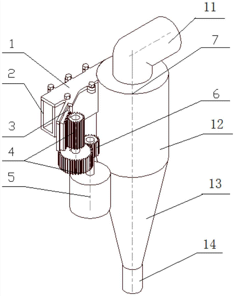
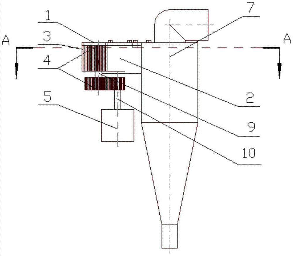
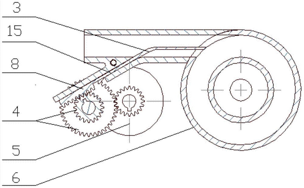
[0021] The invention provides a variable inlet section oil-gas separator, such as figure 1 As shown, it includes the main body 7 of the cyclone oil-gas separator, the intake pipe section 2 with guide grooves, the cover plate of the intake pipe section 1, the sliding plate 3, the reduction gear set 4, the stepping motor 5, and the main body of the cyclone oil-gas separator 7 Including air outlet 11, cylindrical section 12, conical section 13 and oil outlet 14 connected in sequence; stepper motor 5 is provided with stepper motor gear 6; reduction gear set 4 includes upper gear and lower gear connected by gear shaft 9 gears such as image 3 As shown, the end of the sliding piece 3 is a rack 8, the sliding piece 3 is installed in the guide groove 15 of the intake pipe section, and can slide in the intake pipe section 2 along the guide groove, the end of the rack meshes with ...
PUM
 Abstract
Description
Claims
Application Information