Rotary expansion type LED lighting device

An LED lighting and expansion technology, which is applied to lighting devices, lighting auxiliary devices, fixed lighting devices, etc., can solve the problems of fixed mechanism and large use limitations, and achieve the effect of flexible adjustment and improvement of adjustment flexibility.

Pending Publication Date: 2021-06-25
福建省喜德汇科技有限公司
View PDF10 Cites 0 Cited by
  • Summary
  • Abstract
  • Description
  • Claims
  • Application Information

AI Technical Summary

Problems solved by technology

[0003] The mechanism of the existing LED lighting device is relatively fixed, and the adjustment effect of the lighting process cannot be adjusted according to the actual use needs, and the use is limited. Therefore, a rotating and expanding LED lighting device is now provided to solve the above technical problems

Method used


Image

  • Rotary expansion type LED lighting device
  • Rotary expansion type LED lighting device
  • Rotary expansion type LED lighting device

Examples


Embodiment 1

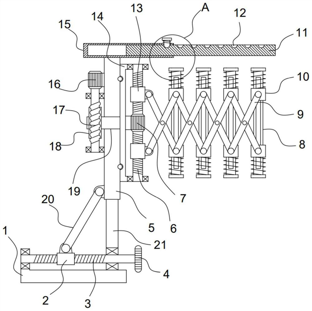
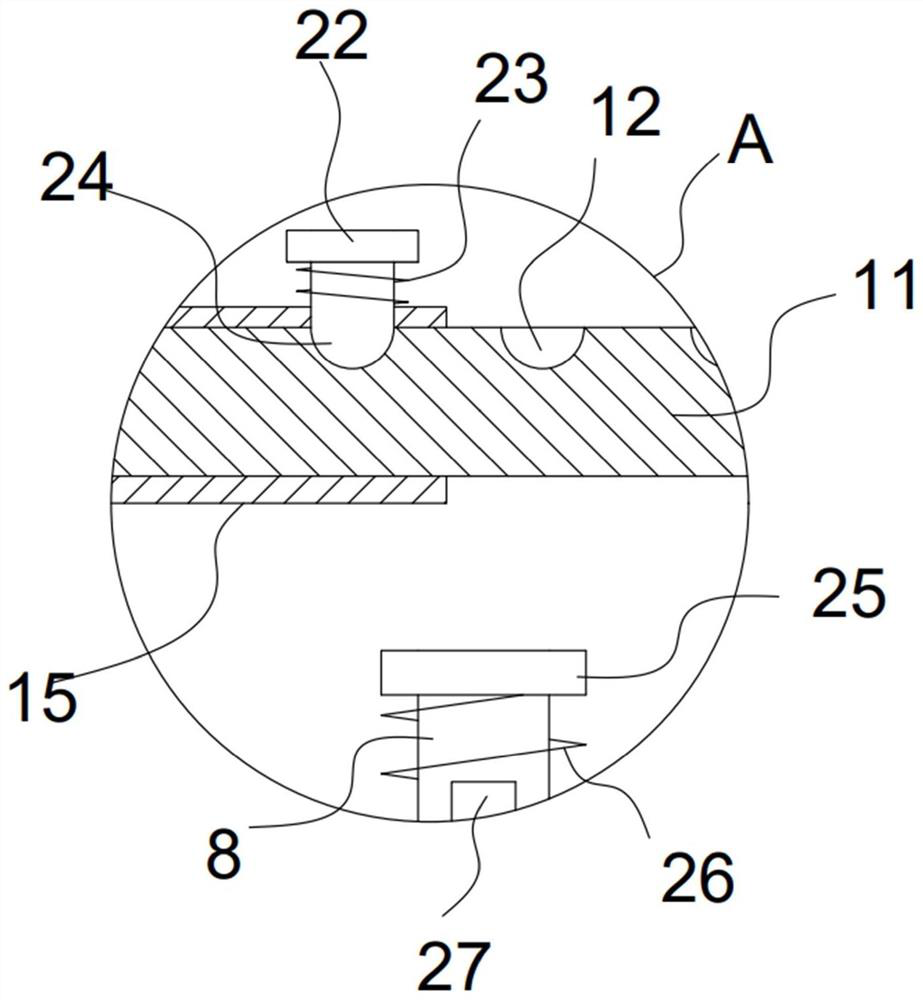
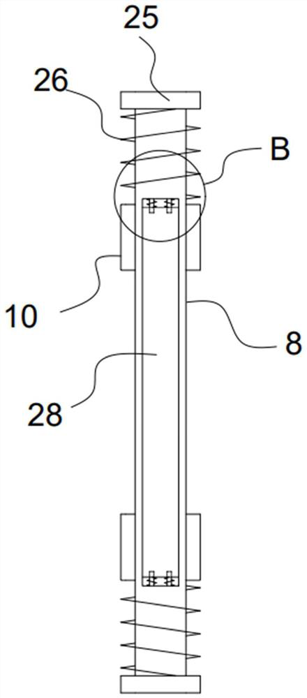
[0024] see Figure 1-5 , a rotating and expanding LED lighting device, comprising a fixed frame 1, a vertical column 21 is vertically fixedly installed on the fixed frame 1, and the vertical column 21 is vertically slidably provided with a sliding sleeve plate 5, and the sliding sleeve plate 5 A lifting mechanism is connected with the fixed frame 1, and the top of the sliding sleeve plate 5 is provided with a shielding protection mechanism, and a servo motor 16 is fixed on the sliding sleeve plate 5, and a rotation adjustment mechanism is driven and connected to the servo motor 16. A turret 14 is installed on the rotation adjustment mechanism, and a double-axis motor 7 is fixed on the turret 14 . The double-axis motor 7 is driven and connected with an expansion mechanism, and the expansion mechanism is provided with a mounting mechanism for being installed on the LED light bar 28 .

[0025] The lifting mechanism of the device includes a threaded rod 3 that is rotatably install...

Embodiment 2

[0031] On the basis of Embodiment 1, in addition, the expansion mechanism of the device includes a biaxial motor 7 fixed on the turret 14, and the two output shafts of the biaxial motor 7 are coaxially fixed with threaded columns 6 with opposite helical directions. , The threaded column 6 is threaded with an adjustment sleeve block 13, and the adjustment sleeve block 13 is hinged with a hinged frame 9.

[0032] The set double-axis motor 7 drives the threaded column 6 to rotate, and the threaded column 6 drives the two adjustment blocks 13 to move toward or away from each other, and then drives the hinged frame 9 to extend or compress, so that the distance between the LED light bars 28 on each installation mechanism Adjusted, when the LED light bars 28 are gathered together, the illumination brightness is higher, and when the LED light bars 28 are scattered, the lighting range is wider, the lighting adjustment is better, and it can be applied to different needs.

[0033] The in...


PUM


Abstract

The invention discloses a rotary expansion type LED lighting device, and relates to the technical field of LED lighting. The rotary expansion type LED lighting device comprises a fixing frame, a vertical stand column is vertically and fixedly mounted on the fixing frame, a sliding sleeve plate vertically sleeves the vertical stand column in a sliding manner, a rotating frame is mounted on a rotary adjusting mechanism, a double-shaft motor is fixed on the rotating frame, an expansion mechanism is in driving connection with the double-shaft motor, and an extension mechanism is provided with an installation mechanism used for being installed on an LED light bar. The height of the LED light bar can be adjusted in a lifting mode through the arranged lifting mechanism, the illumination direction of the LED light bar can be adjusted through the arranged rotary adjusting mechanism, the hinged frame can be telescopically driven through the arranged expansion mechanism, and therefore, the LED light bars installed on the hinged frame through the installation mechanism can be gathered together or scattered, the effect of adjusting the illumination intensity and range is achieved, the adjusting flexibility of the device is greatly improved, and the device can be suitable for flexible adjustment of illumination of various scenes.

Description

technical field [0001] The invention relates to the technical field of LED lighting, in particular to a rotating and expanding LED lighting device. Background technique [0002] LED lighting is light-emitting diode lighting, which is a semiconductor solid-state light-emitting device. It uses a solid semiconductor chip as a light-emitting material. In the semiconductor, the excess energy is released through the recombination of carriers to cause photon emission, and directly emits red, yellow, blue, and green light. On this basis, using the principle of three primary colors, Adding fluorescent powder can emit light of any color. The lighting fixtures manufactured using LEDs as light sources are LED lamps. Among LED lighting fixtures, LED lighting fixtures for reflection purposes can be fully qualified for any occasion, and large-area indoor lighting is not yet mature. [0003] The mechanism of the existing LED lighting device is relatively fixed, and the adjustment effect ...

Claims


Application Information

Patent Timeline
IPC IPC(8): F21S8/00F21V21/36F21V21/30F21V14/02F21Y115/10
CPCF21S8/00F21V21/36F21V21/30F21V14/02F21Y2115/10
Inventor 吴赵平
Owner 福建省喜德汇科技有限公司
Why Eureka
Try Eureka