Ignition device of stove

A technology for ignition devices and stoves, which is applied to household stoves/stoves, lighting and heating equipment, solid heating fuels, etc., can solve the problems of inconvenient operation and long ignition time, achieve short ignition time, simplify the ignition process, and reduce noise effect

Pending Publication Date: 2021-06-25
李来春 +3
View PDF0 Cites 0 Cited by
  • Summary
  • Abstract
  • Description
  • Claims
  • Application Information

AI Technical Summary

Problems solved by technology

[0004] The object of the present invention is to solve the problems of long ignition time and inconvenient operation by proposing an ignition device for a stove aiming at the above-mentioned problems existing in the prior art.

Method used


Image

  • Ignition device of stove
  • Ignition device of stove
  • Ignition device of stove

Examples


Embodiment 1

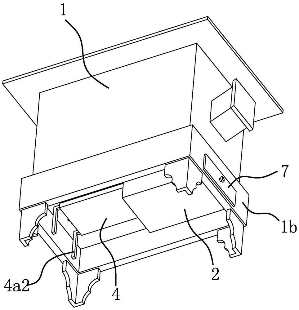
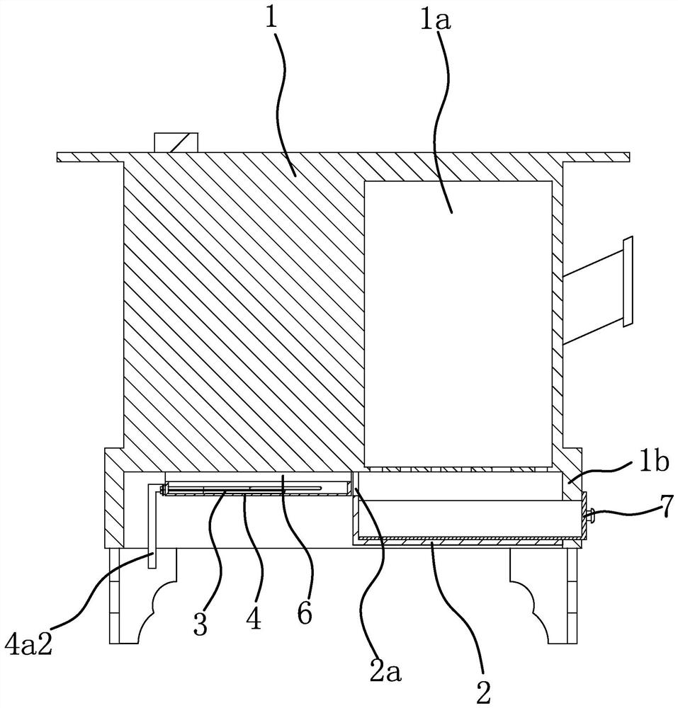
[0044] Such as figure 1 , figure 2 and image 3 As described above, the ignition device of the stove includes a furnace body 1 and an ash collecting box 2 fixed at the bottom of the furnace body 1. The furnace body 1 is made of a metal material and the material of the ash collecting box 2 is the same as that of the furnace body 1. There is a fuel bin 1a in the body 1, and the ash collecting box 2 is located below the fuel bin 1a. The bottom surface of the furnace body 1 is in a grid shape corresponding to the position of the fuel bin 1a, and the top of the ash collecting box 2 is open. After the coal material is ignited, the generated cinders and fly ash will fall into the ash collection box 2 through the mesh at the bottom surface of the furnace body 1 corresponding to the position of the fuel bin 1a. Ash drawer7. Specifically, one side of the lower part of the ash collecting box 2 is open and the bottom of the furnace body 1 has a baffle plate 1b that closes the side ope...

Embodiment 2

[0049] The structure and principle of this embodiment are basically the same as that of Embodiment 1, the difference is that in this embodiment, the support 4 is a supporting plate or a slider that is slidably connected to the two rails 6, and the legs of the shell 3a of the heating element 3 Part 3a2 is fixed on the pallet or slider.

Embodiment 3

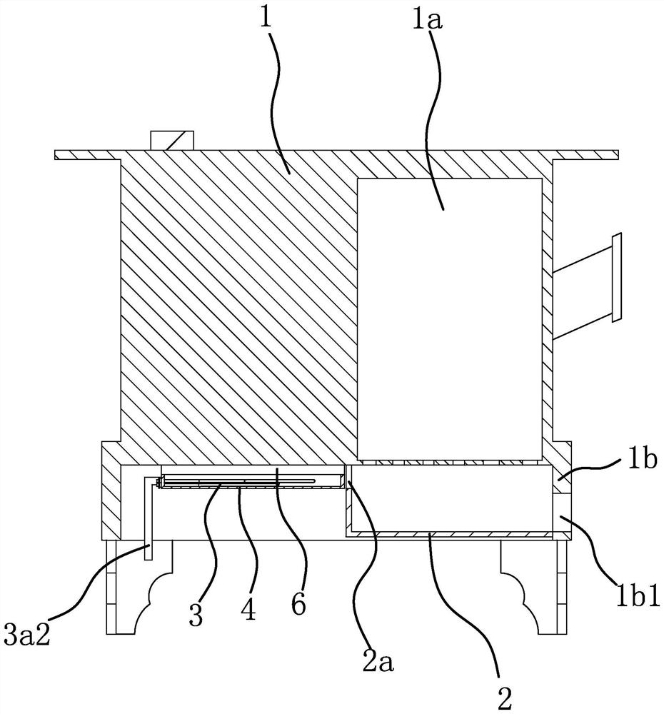
[0051] The structure and principle of this embodiment are basically the same as that of Embodiment 1, the difference is that in this embodiment, a bracket 4 is slidably connected to the upper part of the ash collecting box 2, the electric heating element 3 is fixed on the bracket 4, and the ash collecting box 2 A relief opening 2a through which the bracket 4 can pass is provided through the side.


PUM


Abstract

The invention provides an ignition device of a stove, and belongs to the technical field of household life equipment. The problems of long ignition time and inconvenience in operation are solved. According to the ignition device of the stove, the stove comprises a stove body provided with a fuel bin and an ash collection box fixed to the bottom of the stove body and located below the fuel bin, the ignition device comprises an electric heating piece, a receding opening is formed in the upper portion of one side of the ash collection box in a penetrating mode, and the electric heating piece is connected to the bottom of the stove body and can horizontally move to penetrate through the receding opening into the ash collection box. The ignition device of the stove does not need redundant combustion-supporting materials for ignition, thus noise generated by ignition is reduced while the ignition process is simplified, meanwhile, threat to personal safety can be avoided through the mode that the electric heating piece is pushed into the upper portion of the ash collection box for heating, time and labor are saved, and in addition, the ignition device of the stove has no requirement for the internal space of the ash collection box, so that the structure is simpler and easy to implement, and the device is applicable to stove bodies of any size.

Description

technical field [0001] The invention belongs to the technical field of household living equipment, and relates to a stove, in particular to an ignition device for the stove. Background technique [0002] A coal stove is a common household device, usually consisting of a base and a furnace body. The equipment can heat the stove by adding coal inside the furnace body, so as to realize the functions of home heating, cooking, boiling water and so on. [0003] However, most of the stoves on the market are often ignited by combustibles such as wood and straw, so there are many problems such as inconvenient ignition operation and heavy dust pollution. heating to alleviate the above problems, but there are still some shortcomings in the way of extending the ignition rod into the stove for heating. When igniting, due to the limitation of the shape of the heating rod itself, the heating for the entire stove will cause uneven heating, The problem of long ignition time. At the same ti...

Claims


Application Information

Patent Timeline
Patent Type & Authority Applications(China)
IPC IPC(8): F24B1/191F24B15/00
CPCF24B1/191F24B15/005
Inventor 李来春
Owner 李来春
Why Eureka
Try Eureka