
Water heater control method based on wind pressure sensor and water heater

A technology of wind pressure sensor and control method, which is applied in the directions of fluid heaters, lighting and heating equipment, etc., can solve the problems of wind pressure drop, fan wind attenuation, performance drift, etc., and achieve the effect of avoiding inconvenience

Active Publication Date: 2021-06-25
CHINABEST HOME APPLIANCE
View PDF8 Cites 8 Cited by
  • Summary
  • Abstract
  • Description
  • Claims
  • Application Information

AI Technical Summary

Problems solved by technology

[0003] However, in the actual use of the wind pressure switch, there are the following problems: 1. There are differences in the smoke pipes of gas water heaters in each family, and the resistance of the smoke pipes is not the same. Some gas water heaters have large resistance due to the smoke pipes. The air pressure switch will continue to be off; 2. After the gas water heater has been used for a period of time, the fins of the water tank will accumulate dust, the wind power of the fan will attenuate, the air pressure in the smoke pipe will drop, and the air pressure switch will be disconnected; 3. The external environment changes, the wind will Due to the weather, the resistance of the smoke exhaust port of the smoke pipe increases, the wind pressure of the smoke pipe becomes smaller, and the air pressure switch is disconnected; 4. In order to expand the performance, a fan with two speeds of high and low speeds is designed, and a wind pressure switch cannot guarantee the wind pressure of changing speed Protection, some manufacturers directly cancel the wind pressure protection at low speed, resulting in a risky state without protection; 5. The performance drift of the wind pressure switch, the change of the performance of the diaphragm, etc., will also cause the wind pressure switch to malfunction

Method used


Image

  • Water heater control method based on wind pressure sensor and water heater
  • Water heater control method based on wind pressure sensor and water heater
  • Water heater control method based on wind pressure sensor and water heater

Examples


Embodiment Construction

[0029] The present disclosure provides the following description with reference to the accompanying drawings to help in a comprehensive understanding of various embodiments of the present disclosure as defined by the claims and their equivalents. The description includes various specific details to aid in understanding but these should be regarded as merely exemplary. Accordingly, those of ordinary skill in the art will recognize that various changes and modifications of the various embodiments described herein can be made without departing from the scope and spirit of the disclosure. Also, descriptions of well-known functions and constructions may be omitted for clarity and conciseness.

[0030] The terms and words used in the following description and claims are not limited to the bibliographical meanings, but, are merely used by the inventor to enable a clear and consistent understanding of the present disclosure. Accordingly, it should be apparent to those skilled in the ...


PUM


Abstract

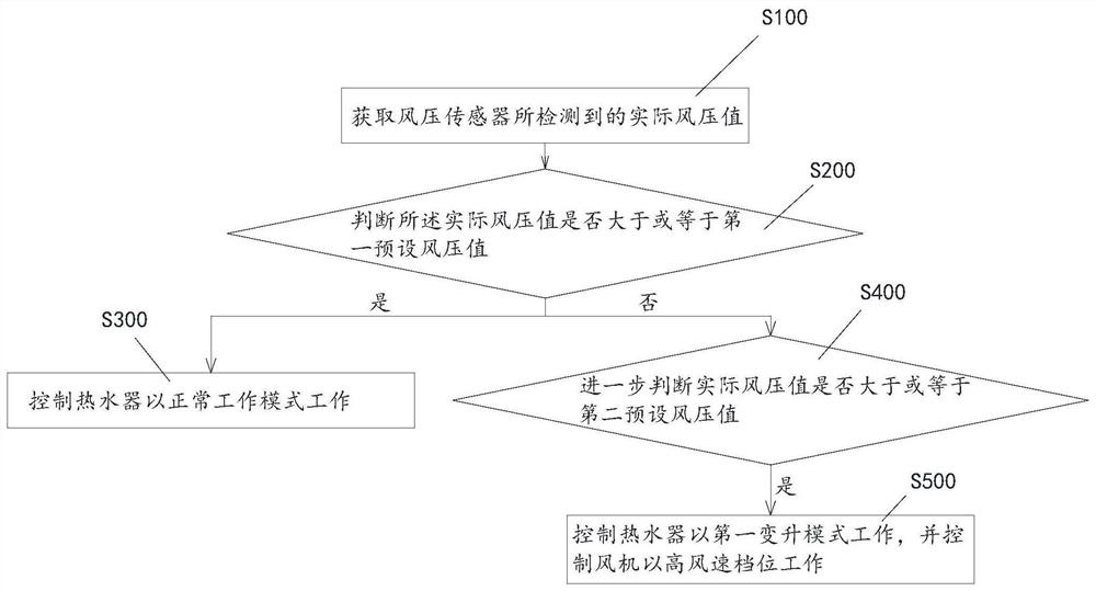
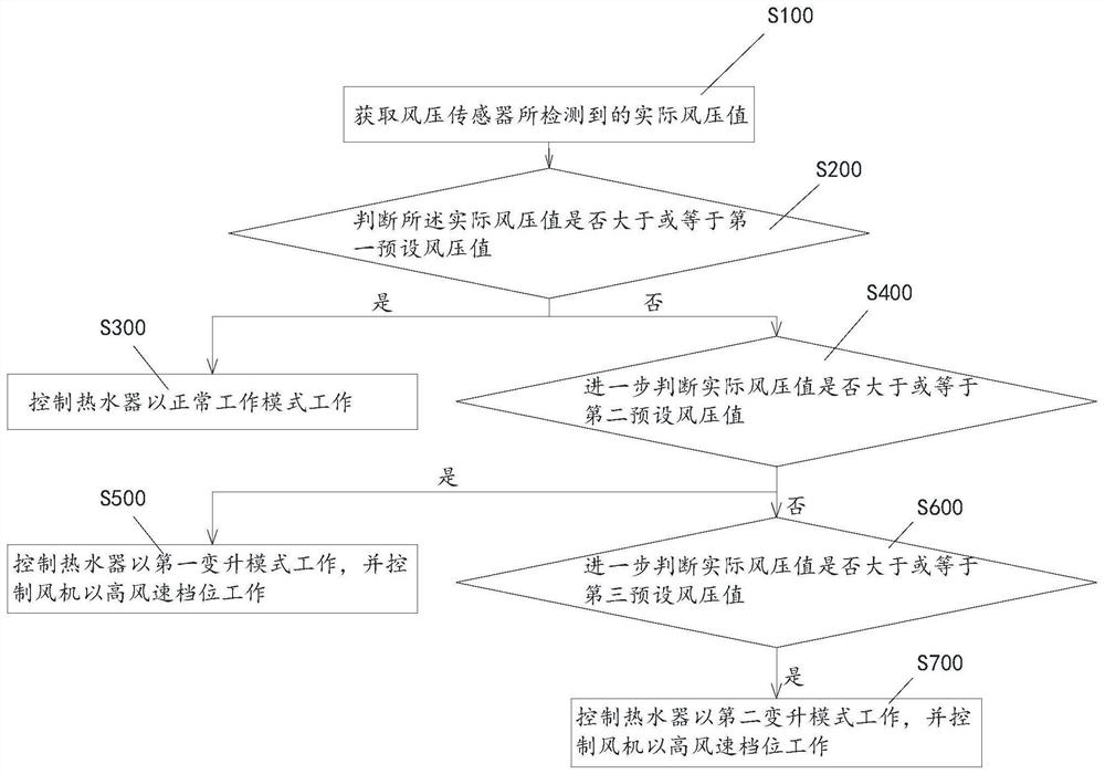
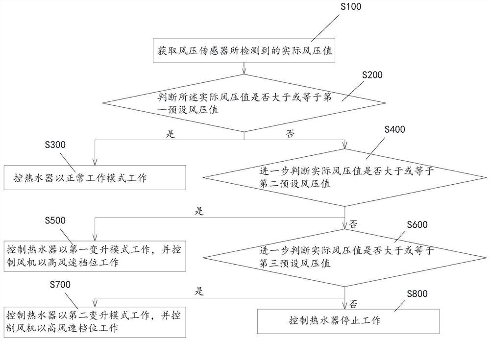
The invention discloses a water heater control method based on a wind pressure sensor and a water heater. The method comprises the following steps that an actual air pressure value detected by the wind pressure sensor is obtained; whether the actual air pressure value is larger than or equal to a first preset air pressure value or not is judged, and if the actual air pressure value is larger than or equal to the first preset air pressure value, the water heater is controlled to work in a normal working mode; if the actual air pressure value is smaller than the first preset air pressure value, whether the actual air pressure value is larger than or equal to a second preset air pressure value or not is further judged, and the second preset air pressure value is smaller than the first preset air pressure value; and if the actual air pressure value is larger than or equal to the second preset air pressure value, the water heater is controlled to work in a first variable-lift mode, and a draught fan is controlled to work at a high-air-speed gear. By means of the water heater control method, the water heater can be more intelligently controlled to work according to air pressure changes.

Description

technical field [0001] The invention relates to the technical field of gas water heaters, in particular to a water heater control method based on a wind pressure sensor and the water heater. Background technique [0002] Gas water heaters generally use a dedicated fan to discharge the exhaust gas from the flue pipe. In order to ensure that the flue gas can be discharged smoothly, the existing gas water heater will be equipped with a wind pressure switch to detect the wind pressure in the flue pipe. If the pressure is low, the wind pressure switch will be disconnected, and the gas water heater will no longer work, which plays a role of safety protection. [0003] However, in the actual use of the wind pressure switch, there are the following problems: 1. There are differences in the smoke pipes of gas water heaters in each family, and the resistance of the smoke pipes is not the same. Some gas water heaters have large resistance due to the smoke pipes. The air pressure switc...

Claims


Application Information

Patent Timeline
IPC IPC(8): F24H9/20
CPCF24H9/2035
Inventor 李强李炳盛朱华春肖建辉
Owner CHINABEST HOME APPLIANCE
Learn More