Method for operating an electrical energy store

An electric accumulator, a technology for storing electric energy, which is applied in the direction of electric devices, electric vehicles, electrical components, etc., and can solve the problems of cost-intensive and other issues

Pending Publication Date: 2021-06-25
ROBERT BOSCH GMBH
View PDF0 Cites 0 Cited by
  • Summary
  • Abstract
  • Description
  • Claims
  • Application Information

AI Technical Summary

Problems solved by technology

Since the safety switch is thus designed for high currents, the safety switch is a cost-intensive and large component

Method used


Image

  • Method for operating an electrical energy store
  • Method for operating an electrical energy store
  • Method for operating an electrical energy store

Examples


Embodiment Construction

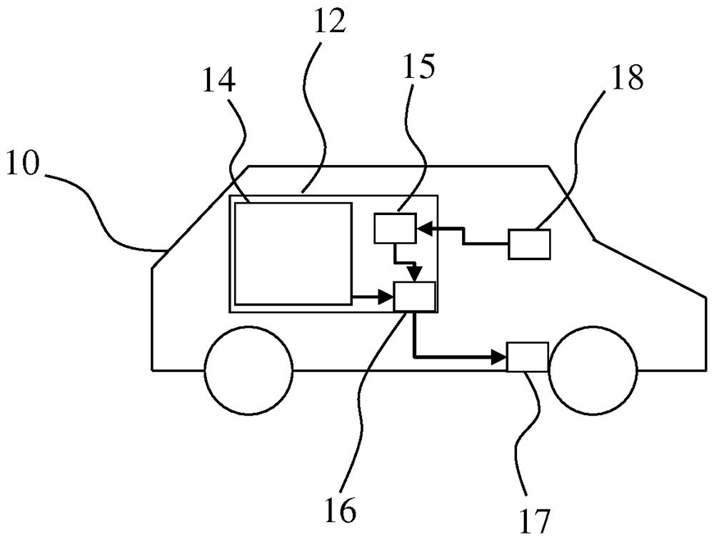
[0014] figure 1 A schematic diagram of an electric vehicle (10) comprising an electric energy storage (12), a vehicle control unit (18) and a drive motor (17) is shown. The electric energy store ( 12 ) in turn comprises a storage unit ( 14 ) and a control unit ( 15 ). A safety switch (16) is arranged on the electric energy store (12), so that the safety switch (16) can interrupt the electric line of the electric energy store (12), via which, for example, the drive motor (17 ) to supply electrical energy. A control unit ( 15 ) of the electric energy store ( 12 ) is connected to the safety switch ( 16 ) via a signal line. The vehicle control unit (18) is connected to the control unit (15) of the electric energy store (12) via a signal line.

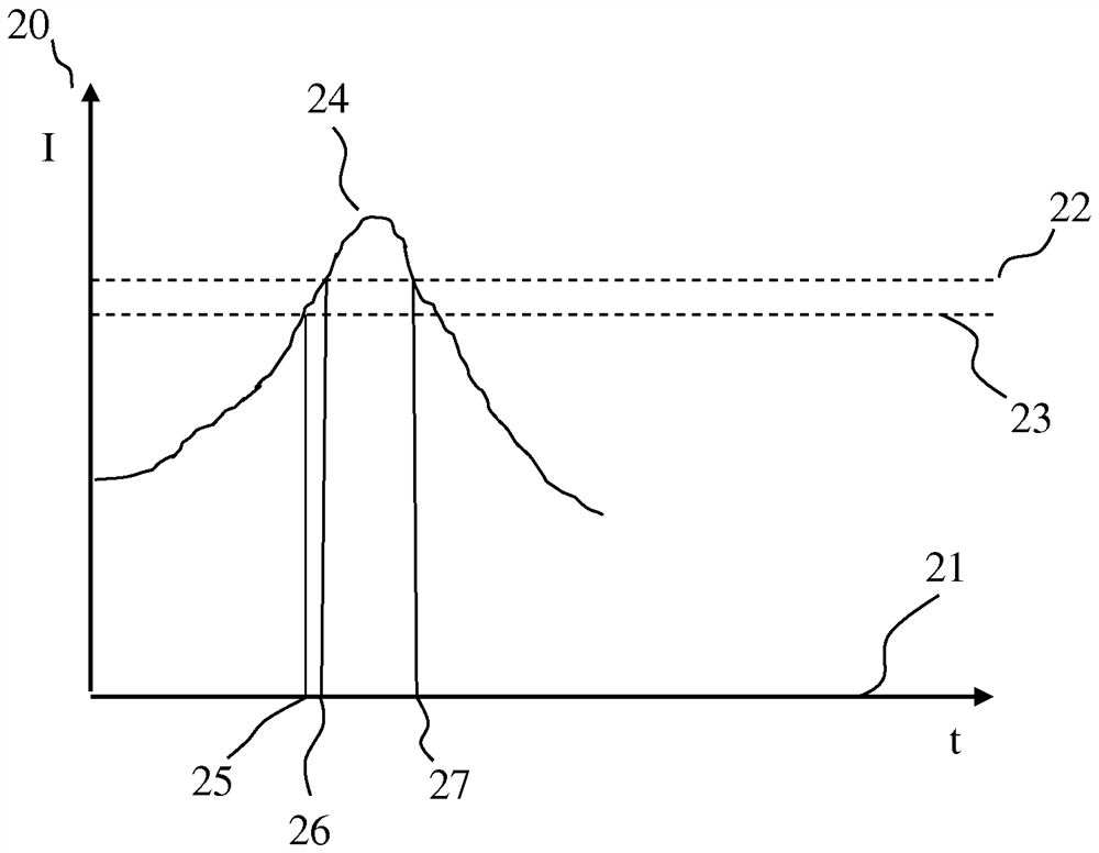
[0015] figure 2 A schematic curve of the current ( 24 ) flowing through the electrical line of the electric energy store ( 12 ) is shown. The current axis is marked with reference number 20 and the time axis with reference number 21 ....


PUM


Abstract

The invention relates to a method for operating an electrical energy store, comprising a storage cell for storing electrical energy and a control unit, wherein a safety switch is provided which is designed to interrupt an electrical line of the electrical energy store, wherein a current flowing through the electrical line is detected and an actuation of the safety switch only occurs if the current is below a predefinable threshold value.

Description

Background technique [0001] Electric energy accumulators, such as those used to operate electric vehicles, are generally secured by means of a safety switch, that is to say a switch is provided which enables the electric The conductive lines inside the accumulator are non-conductive. This trigger signal can be formed, for example, when a fault in the electric energy store is detected (for example, a fault in the energy store itself or a fault in the current sensor) or can also be formed when the vehicle in which the electric energy store is possibly installed is detected. This trigger signal is formed in the event of an accident or in response to an excessive current demand of the vehicle. [0002] Usually, the safety switch is dimensioned in such a way that it can be safely actuated even if a short-circuit current discharged from the electrical energy store flows through the safety switch. Since the safety switch is thus designed for high currents, it is a cost-intensive an...

Claims


Application Information

Patent Timeline
Patent Type & Authority Applications(China)
IPC IPC(8): B60L3/00B60L3/04B60L58/10
CPCB60L3/0046B60L3/04B60L3/0007B60L58/10B60L3/00Y02T10/70H02H3/087H02J7/00304B60L3/12H02J7/0047
Inventor F·戈特瓦尔德R·H·霍尔莱茵T·杜福克斯
Owner ROBERT BOSCH GMBH
Why Eureka
Try Eureka