Auxiliary stress application hammer mechanism for operating rod of electric power system

A power system and operating rod technology, which is applied in the field of power system operating rod auxiliary force hammer mechanism, can solve the problems of fragile isolating switch, affecting the normal operation of the power system, and the difficulty and danger of connecting or disconnecting the isolating switch. , to achieve the effect of easy disconnection or connection operation and improved efficiency

Pending Publication Date: 2022-04-12
刘健
View PDF12 Cites 0 Cited by
  • Summary
  • Abstract
  • Description
  • Claims
  • Application Information

AI Technical Summary

Problems solved by technology

[0003] Although these two devices have more beneficial effects, there are still the following problems: first, the first device still requires the staff to manually switch on or off the high-voltage isolating switch, and to switch on or off the jammed isolating switch. It is still very difficult and dangerous, and although the second device does not require the staff to manually break and connect the high-voltage isolating switch, it uses the rapid impact of the cutter to switch on or off the high-voltage isolating switch. When the isolating switch is stuck, this method can easily damage the isolating switch, or even break the isolating switch, seriously affecting the normal operation of the power system

Method used


Image

  • Auxiliary stress application hammer mechanism for operating rod of electric power system
  • Auxiliary stress application hammer mechanism for operating rod of electric power system
  • Auxiliary stress application hammer mechanism for operating rod of electric power system

Examples


Embodiment Construction

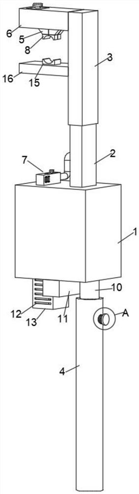
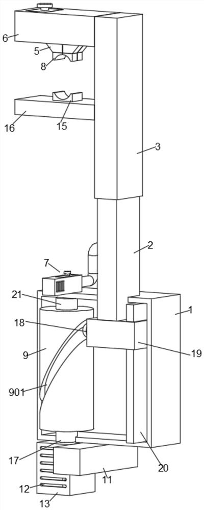
[0027] like figure 1 , Figure 5 As shown, the present invention provides a power system operating rod auxiliary power hammer mechanism, including a mounting box 1, a receiving rod 2, a sliding sleeve 3, a clamping mechanism arranged on the left part of the sliding sleeve, and a clamping mechanism arranged on the installation The adjustment mechanism inside the box is the dust suction assembly arranged on the upper part of the installation box. Specifically, the clamping mechanism includes the storage box 6, the top plate 16 and the first push block 15, the receiving rod 2 is arranged on the upper part of the installation box 1, and the sliding sleeve 3 is set on the upper part of the receiving rod, the left end surface of the sliding sleeve 3 is provided with a storage box 6, the middle part of the left end surface of the sliding sleeve 3 is fixed with a top plate 16, the middle part of the bottom surface of the top plate 16 is provided with a first push block 15, and the top...


PUM


Abstract

The invention discloses an auxiliary stress application hammer mechanism of an electric power system operating rod, and belongs to the technical field of equipment for electric power system maintenance. A power system operating rod auxiliary stress application hammer mechanism comprises a mounting box, a fixing sleeve is arranged below the bottom face of the mounting box, a supporting rod is arranged on the upper side of the circumferential inner wall of the fixing sleeve, a dust collection assembly is arranged on the top face of the fixing sleeve, a motor box is arranged on the bottom face of the fixing sleeve, a first motor is arranged in the motor box, and a main shaft is arranged at the output end of the first motor. The right side of the bottom face of the inner wall of the fixing sleeve is provided with a limiting plate, the outer wall of the limiting plate is sleeved with a movable sleeve, the left side of the top face of the movable sleeve is fixedly provided with a bearing rod, the upper side of the outer wall of the bearing rod is sleeved with a sliding sleeve, and the left end face of the sliding sleeve is provided with a storage box. According to the invention, through cooperation between the first motor arranged in the motor box and the rotating column at the upper end of the main shaft, a jammed isolation switch can be shaken up and down, so that the jammed isolation switch is gradually loosened, and the jammed isolation switch is conveniently switched off and switched on.

Description

technical field [0001] The invention relates to the technical field of equipment for power system maintenance, and more specifically, relates to a power system operating rod auxiliary power hammer mechanism. Background technique [0002] The power system operating rod is a unified name for the insulation tools in the power system, which can be used for live work, live maintenance and live maintenance. Among them, the auxiliary energized hammer used to turn on or off the high-voltage isolating switch is most commonly used in the maintenance of electric equipment. The prior art publication number is CN208208636U, which provides an auxiliary power hammer mechanism for the operation rod of the power system. The device is set between the two impact baffles through the power hammer, so as to realize the impact on both ends respectively. The baffle is impacted to realize the movement of the connecting rod along the two ends of the axial direction; at the same time, when the switch...

Claims


Application Information

Patent Timeline
Patent Type & Authority Applications(China)
IPC IPC(8): H02G1/00H02G1/02H01H3/02H01H31/00B25B11/00
Inventor 刘健
Owner 刘健
Why Eureka
Try Eureka