

Graphene layered composite floor heating plate
A graphene layer and floor heating board technology, applied in the direction of coating, insulation layer, central heating components, etc., can solve the problems of heat loss, complex and cumbersome process, etc., to achieve energy saving, fast heat transfer speed, and improve user experience. Effect
- Summary
- Abstract
- Description
- Claims
- Application Information
AI Technical Summary
Problems solved by technology
Method used
Image


Examples
preparation example Construction
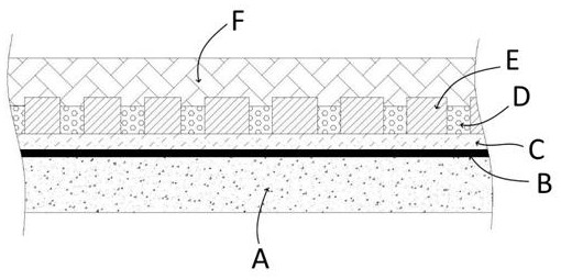
[0037] Based on the structure of the above-mentioned graphene layered composite floor heating board, the present invention also provides a preparation method of a graphene layered composite floor heating board, comprising the steps of:
[0038] S1, preparation of graphene electrothermal filler;
[0039] S2, preparation of graphene electrothermal coating;
[0040] S3, coating of graphene electrothermal coating;
[0041] S4. Assembly of layered composite floor heating panels.
[0042]Since the graphene electrothermal filler used in the present invention is an electrothermal coating, the electrical conductivity of the coating is mainly improved by the conductive filler with high conductivity, and a small amount of palladium powder is added to the electrothermal coating of the present invention to improve the electrical conductivity of the electrothermal coating , far due to the electrothermal coating composed of a single graphene filler. Preferably, the graphene electrothermal...
Embodiment 1
[0056] Step 1. Preparation of graphene electrothermal filler: Dissolve 1Kg graphene powder (N008-P) and 0.1Kg dispersant in ferric chloride solution of saturated concentration, react at high temperature for 3 hours under nitrogen protection, and finally soak Iron oxide nanoparticles were removed in dilute hydrochloric acid, washed with water until neutral, and dried for use; the graphene electrothermal filler was mixed with modified graphene and palladium powder in a mass ratio of 10:1.4.
[0057] Step 2. Preparation of graphene electrothermal coating: Weigh water-based acrylic resin and deionized water according to the mass ratio of 1:1.6, add them to a beaker, mix well and stir until completely dissolved to form a water-based acrylic resin emulsion; take a certain amount according to the ratio Add the water-based acrylic resin emulsion into the beaker, and slowly add a certain amount of dispersant and defoamer additives while mechanically stirring, and finally add the graphen...
Embodiment 2
[0062] Step 1. Preparation of graphene electrothermal filler: Dissolve 1Kg graphene powder (N008-P) and 0.1Kg dispersant in ferric chloride solution of saturated concentration, react at high temperature for 2 hours under nitrogen protection, and finally soak Iron oxide nanoparticles were removed in dilute hydrochloric acid, washed with water until neutral, and dried for use; the graphene electrothermal filler was mixed with modified graphene and palladium powder in a mass ratio of 10:1.
[0063] Step 2. Preparation of graphene electrothermal coating: Weigh water-based acrylic resin and deionized water according to the mass ratio of 1:2, add them to a beaker, mix well and stir until completely dissolved, and form a water-based acrylic resin emulsion; take a certain amount according to the ratio Add the water-based acrylic resin emulsion into the beaker, and slowly add a certain amount of dispersant and defoamer additives while mechanically stirring, and finally add the graphene ...
PUM
 Abstract
Description
Claims
Application Information