Laser processing apparatus and method for determining processing crack

A technology of laser processing and processing marks, which is applied to laser welding equipment, metal processing equipment, manufacturing tools, etc., and can solve the problem of time-consuming

Pending Publication Date: 2021-06-29
DISCO CORP
View PDF1 Cites 0 Cited by
  • Summary
  • Abstract
  • Description
  • Claims
  • Application Information

AI Technical Summary

Problems solved by technology

[0010] However, there is a problem that it is necessary to specify the coordinates of the boundary each time the position of the machining mark is changed, so only operators with specialized knowledge can perform the work, and the work takes time.

Method used


Image

  • Laser processing apparatus and method for determining processing crack
  • Laser processing apparatus and method for determining processing crack
  • Laser processing apparatus and method for determining processing crack

Examples


Embodiment Construction

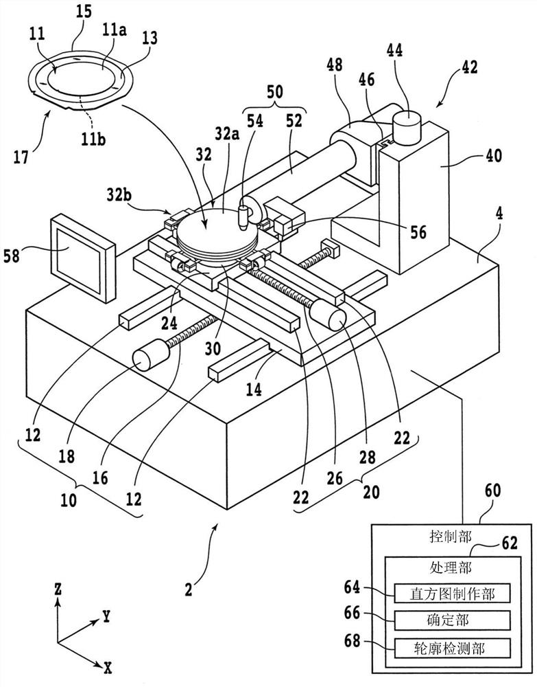
[0028] An embodiment of one embodiment of the present invention will be described with reference to the drawings. figure 1 It is a perspective view of the laser processing device 2 . In addition, in figure 1In , some components of the laser processing apparatus 2 are shown as functional blocks.

[0029] in addition, figure 1 The indicated X-axis direction (left-right direction, machining feed direction, first direction), Y-axis direction (front-back direction, index feed direction, second direction) and Z-axis direction (vertical direction, height direction) are mutually vertical.

[0030] The laser processing device 2 has a cuboid-shaped base 4 that supports each structure. A Y-axis direction moving unit 10 is provided on the upper surface of the base 4 . The Y-axis direction moving unit 10 has a pair of Y-axis guide rails 12 parallel to the Y-axis direction.

[0031] A pair of Y-axis guide rails 12 is fixed on the upper surface of the base 4 . The Y-axis moving table ...


PUM


Abstract

The invention provides a laser processing apparatus and a method for determining a processing crack. The laser processing apparatus automatically determines a boundary of a region in which the processing mark is formed. The laser processing apparatus includes a laser beam irradiation unit which irradiates laser beams have wavelength absorbed by a processed object, an imaging unit, and a processing unit. The processing unit is used for processing the image obtained by the imaging unit and includes a histogram generating section and a determining section. The histogram generating section generates, from an image obtained by the imaging unit imaging a plurality of processing marks formed by applying the laser beam from the laser beam applying unit to a one-surface side of the workpiece, a first histogram including a plurality of first positions along a first direction of the image and brightness at each of the first positions and a second histogram including a plurality of second positions along a second direction orthogonal to the first direction and brightness at each of the second positions. The determining section determines a boundary of each region where one of the processing marks is formed, based on the first histogram and the second histogram generated by the histogram generating section.

Description

technical field [0001] The present invention relates to a laser processing apparatus for forming a plurality of processing marks by irradiating a laser beam on one surface side of a workpiece, and a method for confirming the region where each processing mark exists. Background technique [0002] In a laser processing apparatus that processes a workpiece by irradiating the workpiece with a laser beam having a wavelength absorbed by the workpiece, the shape of the laser beam affects processing quality. For example, after actually processing the workpiece with the laser beam, the shape of the laser beam is confirmed by observing the processing result. [0003] In one example, when using a laser beam to linearly process one side of a flat plate-shaped workpiece, first, the side opposite to the one surface of the workpiece is paired using a holding table provided in a laser processing device. Hold on the other side. Next, the holding table is moved in a predetermined direction ...

Claims


Application Information

Patent Timeline
Patent Type & Authority Applications(China)
IPC IPC(8): B23K26/00B23K26/03B23K26/08
CPCB23K26/00B23K26/032B23K26/0853B23K26/0869B23K2103/56B23K26/0676B23K26/0736B23K26/048B23K26/0006B23K26/40H01L21/3043B23K26/707
Inventor 河野文弥
Owner DISCO CORP
Why Eureka
Try Eureka