Thermal instrument junction box mounting device

A technology for thermal instruments and installation devices, which is applied in cable installation devices, workpiece clamping devices, cable installation, etc. It can solve the problems of junction box installation interference, block installation hole positions, and adjust clamping force, etc., and achieve good results. Clamping effect, the effect of reducing the difficulty of installation

Pending Publication Date: 2021-06-29
天长市旭升热工仪表配件有限公司
View PDF0 Cites 0 Cited by
  • Summary
  • Abstract
  • Description
  • Claims
  • Application Information

AI Technical Summary

Problems solved by technology

[0003] The existing thermal instrument junction box usually needs to be well sealed during installation. The existing junction box usually uses pliers and C-shaped pliers to assist in the installation, and the pliers cannot be easily adjusted and clamped. However, C-shaped pliers and pliers have the problem of blocking the installation hole when clamping, which will interfere with the installation of the junction box, and the installation of C-shaped pliers and pliers is more dependent on manual force, and it is more difficult to use. strenuous

Method used


Image

  • Thermal instrument junction box mounting device
  • Thermal instrument junction box mounting device
  • Thermal instrument junction box mounting device

Examples


Embodiment Construction

[0033] The following will clearly and completely describe the technical solutions in the embodiments of the present invention with reference to the accompanying drawings in the embodiments of the present invention. Obviously, the described embodiments are only some, not all, embodiments of the present invention. Based on the embodiments of the present invention, all other embodiments obtained by persons of ordinary skill in the art without making creative efforts belong to the protection scope of the present invention.

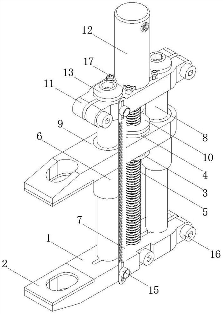
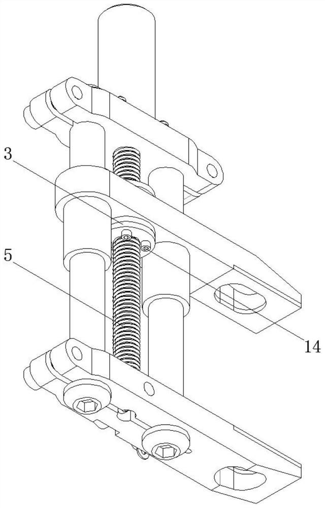
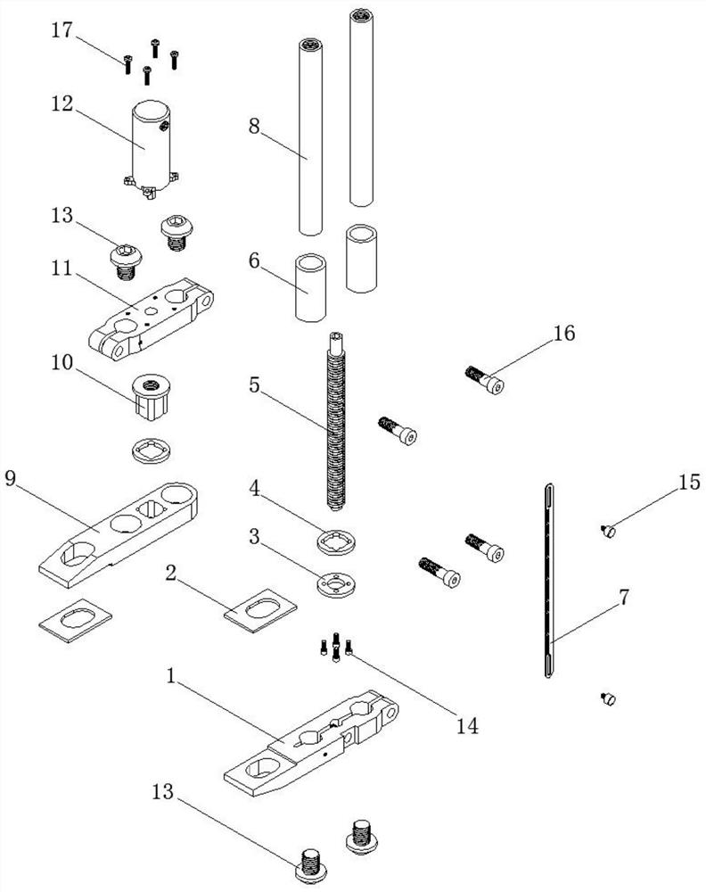
[0034] The present invention provides such Figure 1-15 The shown installation device for a thermal instrument junction box includes a lower clip 1, a lower piece 3, a buffer pad 4, a threaded shaft 5, a sleeve 6, a scale 7, a vertical shaft 8, an upper clip 9, and a rotation inhibiting block 10. Top bar 11, motor 12 and control box 18. The lower clip bar 1 and the top bar 11 are sleeved on the lower and upper ends of the two vertical shafts 8 respectively, an...


PUM


Abstract

The invention discloses a thermal instrument junction box mounting device. The device comprises a lower clamping strip, a lower piece, buffering pads, a threaded shaft, sleeves, a graduated scale, vertical shafts, an upper clamping strip, a rotation restraining block, a top strip, a motor and a control box, wherein the lower clamping strip and the top strip sleeve the lower ends and the upper ends of the two vertical shafts respectively, the outer circles of the vertical shafts are sleeved with the sleeves in sliding connection with the vertical shafts, the upper clamping strip sleeve the two sleeves, the lower clamping strip and the upper clamping strip are each bonded with a cushion block, the top strip and the lower clamping strip are tightened and clamped through strip screws, the motor is fixed above the top strip, the threaded shaft is arranged between the top strip and the lower clamping strip, the rotation restraining block in threaded connection with the threaded shaft is arranged in the middle of the threaded shaft, the lower piece is fixed to the lower end of the rotation restraining block, the rotation restraining block is sleeved with the two buffering pads, and the upper clamping strip is located between the two buffering pads. The thermal instrument junction box mounting device can uniformly and stably press an instrument junction box, and is suitable for being widely popularized and used.

Description

technical field [0001] The invention belongs to the technical field of thermal instruments, in particular to a junction box installation device for thermal instruments. Background technique [0002] Thermal instruments mainly include pressure gauges, pressure transmitters, differential pressure transmitters, pressure calibrators, thermal signal calibrators; in-situ thermometers, thermal resistances, thermocouples, liquid level transmitters, temperature transmitters Devices, pressure sensors, liquid level transmitters, liquid level gauges, intelligent digital displays, flash alarms, paperless recorders, flow totalizers, pressure calibration devices and temperature calibration devices, etc. [0003] The existing thermal instrument junction box usually needs to be well sealed during installation. The existing junction box usually uses pliers and C-shaped pliers to assist in the installation, and the pliers cannot be easily adjusted and clamped. However, C-shaped pliers and pli...

Claims


Application Information

Patent Timeline
IPC IPC(8): B25B27/00B25B11/02H02G1/00
CPCB25B11/02B25B27/00H02G1/00
Inventor 陈军
Owner 天长市旭升热工仪表配件有限公司
Why Eureka
Try Eureka