
Fitting method, fitting jig and display device

A bonding jig and bonding technology, applied in the direction of lamination devices, chemical instruments and methods, layered products, etc., can solve the problems of difficult module bonding and poor bonding, and reduce the overall bonding difficulty. , The effect of uniform force and avoiding damage

Active Publication Date: 2021-06-29
YUNGU GUAN TECH CO LTD
View PDF10 Cites 3 Cited by
  • Summary
  • Abstract
  • Description
  • Claims
  • Application Information

AI Technical Summary

Problems solved by technology

For curved surface bonding, especially when the bending angle of some curved surface covers is greater than 90 degrees, the overall bonding of the display module is difficult and prone to poor bonding

Method used


Image

  • Fitting method, fitting jig and display device
  • Fitting method, fitting jig and display device
  • Fitting method, fitting jig and display device

Examples


Embodiment Construction

[0037] In order to make the purposes, technical solutions and advantages of the embodiments of the present application clearer, the technical solutions in the embodiments of the present application will be clearly and completely described below in conjunction with the drawings in the embodiments of the present application. Obviously, the described embodiments It is a part of the embodiments of this application, not all of them. The components of the embodiments of the application generally described and illustrated in the figures herein may be arranged and designed in a variety of different configurations.

[0038] Accordingly, the following detailed description of the embodiments of the application provided in the accompanying drawings is not intended to limit the scope of the claimed application, but merely represents selected embodiments of the application. Based on the embodiments in this application, all other embodiments obtained by persons of ordinary skill in the art w...


PUM


Abstract

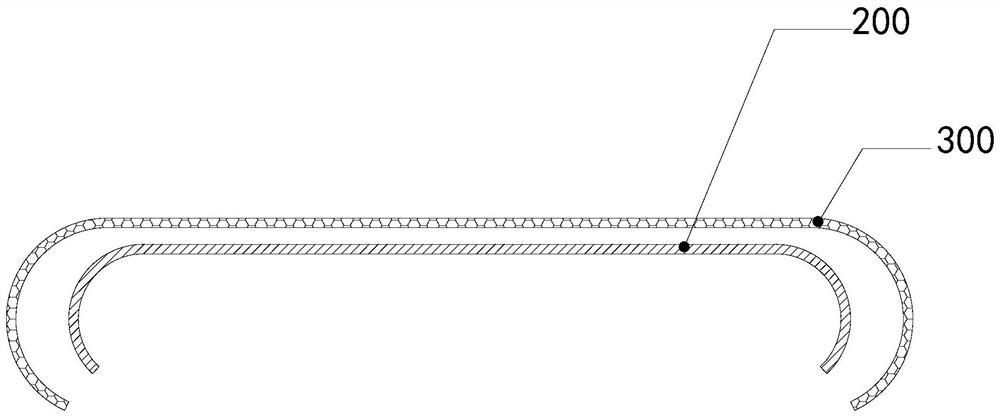
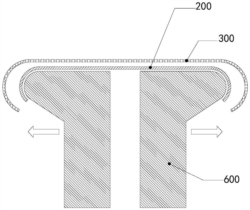
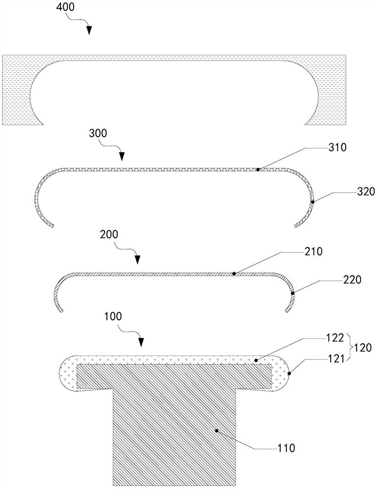
The embodiment of the invention provides a curved surface display module fitting method, a fitting jig and a display device; fitting of the plane part of a display module is completed by the press-fit part which conforms to the plane part of the display module in shape in the fitting jig, then the press-fit part extrudes a filler in an accommodating bag to move towards the curved surface part of the display module, and thus fitting of the curved surface part is completed. Therefore, it can be guaranteed that the plane part is evenly stressed in the fitting process, wrinkles are avoided, friction shear force generated in the fitting process of the curved surface part is avoided or friction shear force possibly generated in the fitting process is at least reduced through movement of the filler towards the direction of the curved surface part after the filler is extruded, and the display module is prevented from being damaged.

Description

technical field [0001] The present application relates to the field of display technology, in particular, to a bonding method, a bonding fixture and a display device. Background technique [0002] In order to improve the display effect of the screen, in some display devices, the display module and the curved cover plate are curved-bonded to prepare a curved display device. For curved surface bonding, especially when the bending angle of some curved surface covers is greater than 90 degrees, the overall bonding of the display module is difficult and prone to poor bonding. Contents of the invention [0003] In order to overcome the technical problems mentioned in the above technical background, the embodiments of the present application provide a lamination method, a lamination jig, and a display device. [0004] In the first aspect, the bonding method provided in this embodiment is used to bond the display module to the curved cover; the curved cover includes a first plana...

Claims


Application Information

Patent Timeline
Patent Type & Authority Applications(China)
IPC IPC(8): B32B37/00B32B37/10
CPCB32B37/0015B32B37/10
Inventor 赵建潮
Owner YUNGU GUAN TECH CO LTD
Learn More