Winding device for warp knitting fabric production

A warp-knitted fabric and No. 1 technology, which is applied in the field of warp-knitted fabric production, can solve the problems of rollover, fixation, and uneven force on the left and right sides of the roll-up device, so as to improve safety, The effect of preventing rollover

Pending Publication Date: 2021-06-29
海宁凯兴新材料股份有限公司
View PDF7 Cites 3 Cited by
  • Summary
  • Abstract
  • Description
  • Claims
  • Application Information

AI Technical Summary

Problems solved by technology

[0002] Warp-knitted fabric is knitted or woven through a warp-knitted textile process. In the production process of warp-knitted fabric, it is necessary to use a winding device to wind up the warp-knitted fabric. The winding device has a small footprint, Simple structure and other advantages; but the existing winding device still has certain disadvantages in use, first of all, the width of the winding drum of the existing winding device is fixed, so the winding drum can only be used for a specific The warp-knitted fabric of the same size is rolled up, which leads to the limitation of the winding device. Secondly, the existing winding device needs to rewind the warp-knitted fabric when the user unloads the warp-knitted fabric. The warp knitted fabric can only be unloaded by removing one side of the device bracket. During the unloading process, the force on the left and right of the winding device is uneven, resulting in the risk of rollover of the winding device. For this reason, we propose a Retracting device for warp knitted fabric production

Method used


Image

  • Winding device for warp knitting fabric production
  • Winding device for warp knitting fabric production
  • Winding device for warp knitting fabric production

Examples


Embodiment Construction

[0019] The following will clearly and completely describe the technical solutions in the embodiments of the present invention with reference to the accompanying drawings in the embodiments of the present invention. Obviously, the described embodiments are only some, not all, embodiments of the present invention.

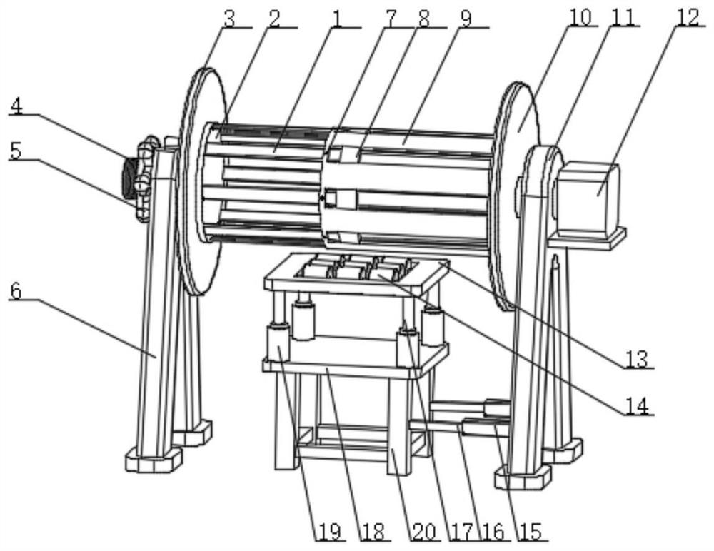
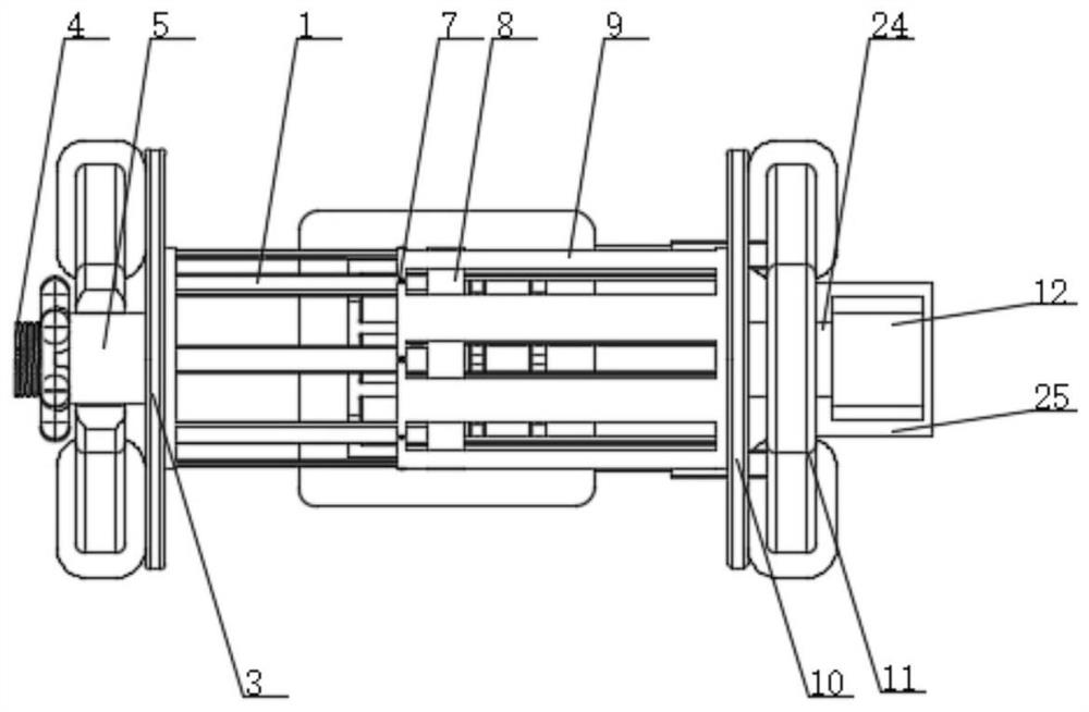
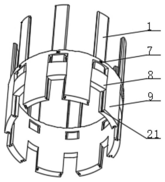
[0020] refer to Figure 1-4 , a retracting device for the production of warp knitted fabrics, comprising a telescopic rod 1, the side end of the telescopic rod 1 is provided with a fixed plate 2, and the side end of the fixed plate 2 is provided with a No. 1 limit plate 3, a No. 1 limit plate The side end of 3 is provided with threaded rod 4, and the outer surface of threaded rod 4 is provided with fixed handle 5, and the lower end of fixed handle 5 is provided with No. 1 support frame 6, and the side end of telescopic rod 1 is provided with limit block 8, limit block 8 The side end of the limit sleeve 9 is provided with a limit sleeve 9, the inner side of the limit ...


PUM


Abstract

The invention discloses a winding device for warp knitting fabric production. The device comprises a telescopic rod, a fixing plate is arranged at the side end of the telescopic rod, a first limiting plate is arranged at the side end of the fixing plate, a threaded rod is arranged at the side end of the first limiting plate, a fixing handle is arranged on the outer surface of the threaded rod, a first supporting frame is arranged at the lower end of the fixing handle, a limiting block is arranged at the side end of the telescopic rod, a limiting sleeve is arranged at the side end of the limiting block, and a jackscrew is embedded in the inner side of the limiting sleeve. According to the winding device for warp knitting fabric production, through cooperation of the telescopic rod, the limiting sleeve, the limiting block and the jackscrew, the width of a winding structure can be adjusted, the limitation of overall use of the device is reduced, and through cooperation of a bearing wheel, a supporting plate, a limiting shaft and a spring, when a user disassembles wound fabric, the fabric is supported, and a device main body is prevented from rolling over.

Description

technical field [0001] The invention relates to the field of cloth production, in particular to a retracting device for warp knitted cloth production. Background technique [0002] Warp-knitted fabric is knitted or woven through a warp-knitted textile process. In the production process of warp-knitted fabric, it is necessary to use a winding device to wind up the warp-knitted fabric. The winding device has a small footprint, Simple structure and other advantages; but the existing winding device still has certain disadvantages in use, first of all, the width of the winding drum of the existing winding device is fixed, so the winding drum can only be used for a specific The warp-knitted fabric of the same size is rolled up, which leads to the limitation of the winding device. Secondly, the existing winding device needs to rewind the warp-knitted fabric when the user unloads the warp-knitted fabric. The warp knitted fabric can only be unloaded by removing one side of the devic...

Claims


Application Information

Patent Timeline
Patent Type & Authority Applications(China)
IPC IPC(8): B65H18/02B65H75/24B65H19/30B65H18/10
CPCB65H18/028B65H75/241B65H19/30B65H18/10B65H2701/1133
Inventor 何凯玲郭凯兴
Owner 海宁凯兴新材料股份有限公司
Why Eureka
Try Eureka