
An electric valve for intelligent irrigation and its application

A technology of using electric valve and intelligent irrigation, applied in the field of electric control transmission, can solve the problems of reducing the service life of electric valve, failure of electric valve, inconvenient use, etc., and achieve the effect of improving practicability and prolonging service life.

Active Publication Date: 2021-11-05
北京国垦节水科技有限公司
View PDF2 Cites 0 Cited by
  • Summary
  • Abstract
  • Description
  • Claims
  • Application Information

AI Technical Summary

Problems solved by technology

[0003] In the prior art, Patent No. 201710152721.8 and Patent No. 201610378228.3 disclose an electric valve, which solves the problem that due to the large pipeline flow and large water pressure, the use of traditional manual valves is time-consuming, laborious, and inconvenient to use. Meeting the Problems of Current Smart Irrigation Systems
[0004] However, in actual use, the electric valve often fails. The main reason is that the impact force in the direction of the water flow generated by the water flow will bring greater resistance to the rotating core (spherical or thin cylinder) of the electric valve when the valve is braked. The electric mechanism greatly reduces the service life of the electric valve, increases the maintenance cost, and delays the optimal irrigation time;
[0005] In addition, most of the electric valves on the market have only one or two water outlets, so the controlled irrigation area is limited. In addition, the electric valve is expensive, and the number of electric valves needs to be increased to control a larger irrigation area, which undoubtedly increases the cost of agricultural irrigation equipment.

Method used


Image

  • An electric valve for intelligent irrigation and its application
  • An electric valve for intelligent irrigation and its application
  • An electric valve for intelligent irrigation and its application

Examples


Embodiment 1

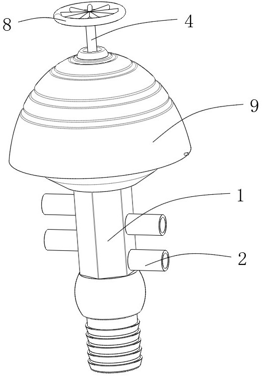
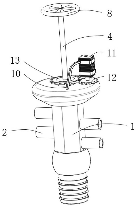
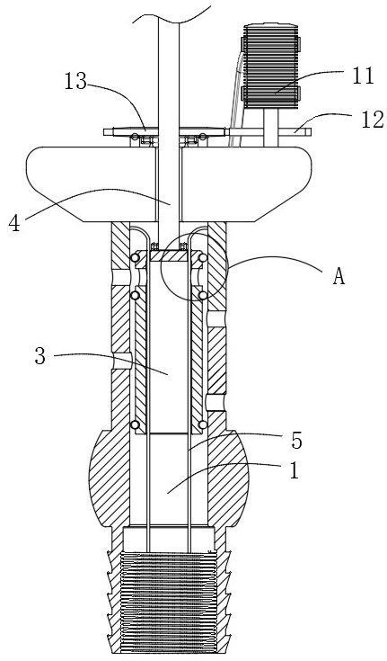
[0037] Example 1, such as Figure 1-9 As shown, an electric valve for intelligent irrigation is mainly composed of a valve body 1, a valve core 3, a through hole 7, a driving mechanism, and four outlet pipes 2 connected to both sides of the valve body 1. The valve body 1 and the valve The cores 3 are all cylindrical structures with openings facing downwards. The valve cores 3 slide on the inner wall of the valve body 1. The through holes 7 run through both sides of the valve core 3 horizontally. The surface of the valve body 1 is opposite to the outlet pipe 2. There are four circular holes in the position, and the four circular holes are sequentially staggered in the axial direction of the valve body 1 and staggered by a certain angle in the circumferential direction. The shaped holes communicate with the four outlet pipes 2 respectively, the through holes 7 are circular holes, the inner diameter of the circular holes is smaller than the inner diameter of the through holes 7, ...


PUM


Abstract

The invention provides an electric valve for intelligent irrigation and its application, relates to the technical field of tank cover valves, and is mainly composed of a valve body, a valve core, a through hole, a driving mechanism and outlet pipes connected to both sides of the valve body. Both the valve core and the valve core are cylindrical structures with openings facing. The valve core slides on the inner wall of the valve body. The through hole runs through both sides of the valve core horizontally. The driving mechanism is located between the valve core and the valve body to drive The spool slides up and down on the inner wall of the valve. In the present invention, the force of the water flow and the force of controlling the spool are on the same straight line, so that the resultant force between the water flow force and the control force of the spool when the spool is controlled and the two forces are not on the same straight line will not cause the spool to deviate. The problem that the force is easy to damage the valve core greatly prolongs the service life.

Description

technical field [0001] The invention relates to the technical field of electric control transmission, in particular to an electric valve for intelligent irrigation and its application. Background technique [0002] In intelligent irrigation systems, solenoid valves or electric valves are usually used. Solenoid valves are often installed at the head of the irrigation system, which require wires for communication, have high requirements for water quality, and have limited control areas; electric valves are often installed at the field water supply hydrants. Electric storage media (such as batteries, solar panels) realize electric control and remote intelligent irrigation communication, and realize the rotation irrigation of large-scale crops. [0003] In the prior art, Patent No. 201710152721.8 and Patent No. 201610378228.3 disclose an electric valve, which solves the problem that due to the large pipeline flow and large water pressure, the use of traditional manual valves is ...

Claims


Application Information

Patent Timeline
Patent Type & Authority Patents(China)
IPC IPC(8): F16K11/07F16K27/04F16K31/05A01G25/02A01G25/16
CPCA01G25/02A01G25/16F16K11/0716F16K27/041F16K31/05
Inventor 屈英尹飞虎郝晓东王海涛
Owner 北京国垦节水科技有限公司
Learn More