
Device and method for detecting change of reflected light

A technology of reflected light and reflected beam, which is applied in measurement devices, optical devices, polarization effects, etc., can solve the problems of increased use of optical components, extremely high requirements, and difficult rate of change of spot energy decomposition, and achieves improved changes. The effect of detection rate

Active Publication Date: 2021-06-29
SHANGHAI PRECISION MEASUREMENT SEMICON TECH INC
View PDF5 Cites 0 Cited by
  • Summary
  • Abstract
  • Description
  • Claims
  • Application Information

AI Technical Summary

Problems solved by technology

[0005] However, in the above-mentioned technical solution, there are the following problems: the first problem is that the position adjustment accuracy of the first reflector 6c of the applied optical system is extremely high, and its stability is also extremely high. Undertake the role of beam splitting, the requirements for the alignment and stability of the optical path are high, and the assembly of the optical path is relatively difficult; the second aspect is reflected in the complexity of the optical path, which requires the assembly of the first reflector 6c and the second reflector 6d respectively , and in order to meet the requirement that the incident light within a certain angle can be effectively reflected and refracted, the parallel collimation and field of view interlacing between the two also need to be precisely adjusted for a design, and at the same time, two detectors are required to detect the outgoing light. The increase in the use of optical components will also lead to an increase in cost; the third aspect is reflected in the detection accuracy. Due to the use of light splitting in the optical path, the transmitted and reflected light is further lost. The change rate of energy decomposition is more difficult to detect, so the detection signal-to-noise ratio is low, about one part per million, and the requirements for the divergence angle of the detection beam waist are extremely high

Method used


Image

  • Device and method for detecting change of reflected light
  • Device and method for detecting change of reflected light
  • Device and method for detecting change of reflected light

Examples


Embodiment approach

[0074] According to another embodiment of the present invention, a method for obtaining reflected light detection changes in acousto-optic detection is proposed, the method includes:

[0075] Using the first pupil divider to perform field intensity division of the incident light beam so that the incident light beam forms a first field intensity distribution on the first surface of the first pupil divider;

[0076] converging the incident beam with the first field intensity distribution obliquely incident on the surface of the object to form a reflected beam with the second field intensity distribution;

[0077] receiving a reflected beam having a second field strength distribution and collimating to form a reflected beam having a third field strength distribution;

[0078] Using the second pupil divider to receive the reflected beam with the third field intensity distribution for field intensity division, so that the reflected beam with the third field intensity distribution f...


PUM


Abstract

The invention provides a device and method for detecting change of reflected light. The method comprises the following steps of performing field intensity segmentation on an incident light beam by using a first pupil splitter so as to enable the incident light beam to form the first field intensity distribution on a first surface of the first pupil splitter; collimating and converging the incident light beam with the first field intensity distribution to obliquely irradiate the surface of an object so as to form a reflected light beam with second field intensity distribution; receiving the reflected light beam with the second field intensity distribution and collimating to form a reflected light beam with the third field intensity distribution; performing field intensity segmentation on the reflected light beam with the third field intensity distribution by using the position and the shape of a second pupil splitter so as to enable the reflected light beam with the third field intensity distribution to form the fourth field intensity distribution on the first surface of the second pupil splitter, wherein the first pupil splitter and the second pupil splitter have the same aperture function distribution; and obtaining the reflected light beam with the fourth field intensity distribution, and analyzing the change information of the reflected light beam with the fourth field intensity distribution in a time interval, so that the signal change formed by the light intensity change and the imaging position deviation after analysis is enhanced, and the signal-to-noise ratio of a detector is improved.

Description

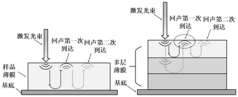
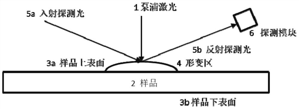
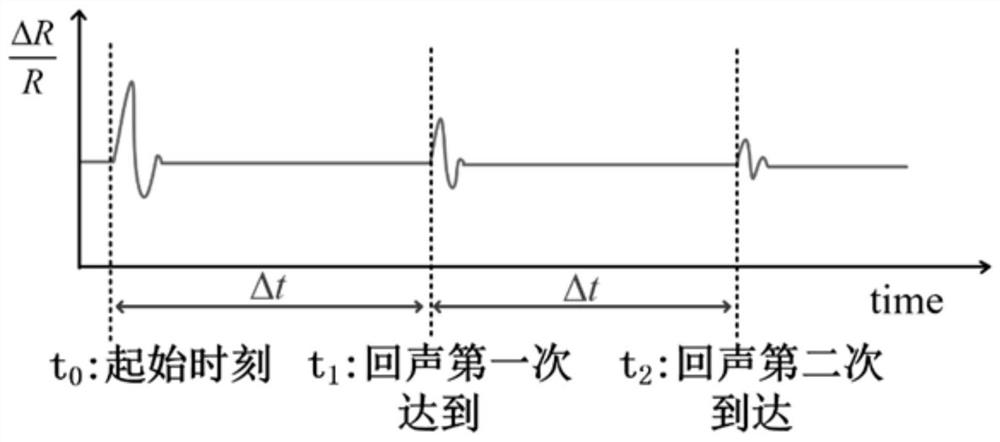
technical field [0001] The invention belongs to an acousto-optic measuring system and is mainly used for measuring metal films and dielectric films. Specifically, it relates to a device and method for detecting changes in reflected light. Background technique [0002] At present, the principle of acousto-optic measurement in the prior art is as follows: the short-pulse laser is irradiated on the surface of the film sample, and the film sample absorbs photons to generate thermoelastic deformation, and the surface forms a deformation zone; the thermoelastic deformation generates sound waves that propagate on the solid surface and inside; longitudinal sound waves The first echo signal is generated at the interface (the junction of the substrate or the film and the film); the first echo signal reaches the upper surface, causing further changes in the deformation; the echo signal rebounds after hitting the upper surface, and rebounds After touching the interface, a second echo si...

Claims


Application Information

Patent Timeline
Patent Type & Authority Applications(China)
IPC IPC(8): G01B11/06
CPCG01B11/06G01B11/0625G01B11/0641G01B11/0675G01N21/1702G01N21/21G01N21/8422
Inventor 王奇李仲禹王政
Owner SHANGHAI PRECISION MEASUREMENT SEMICON TECH INC
Learn More