Device and method for detecting angle change of reflected light beam and film thickness measuring device

A technology of reflected beams and incident beams, applied in measuring devices, optical devices, instruments, etc., can solve the problems of difficult change rate of spot energy decomposition, low detection signal-to-noise ratio, transmission and reflection light loss, etc., to improve change detection High efficiency, improved detection accuracy, single polarization state effect

Active Publication Date: 2021-07-23
SHANGHAI PRECISION MEASUREMENT SEMICON TECH INC
View PDF8 Cites 0 Cited by
  • Summary
  • Abstract
  • Description
  • Claims
  • Application Information

AI Technical Summary

Problems solved by technology

[0005] However, in the above-mentioned technical scheme, there are the following problems: the first problem is that the position adjustment accuracy of the first reflector 6c of the applied optical system is extremely demanding High, and its stability is also extremely high, the optical element undertakes the role of splitting the field intensity of the light spot, the requirements for the alignment and stability of the optical path are high, and the assembly of the optical path is relatively difficult; the second aspect is reflected in In terms of the complexity of the optical path, it is necessary to assemble the first reflector 6c and the second reflector 6d respectively, and in order to meet the requirement that the incident light within a certain angle can be effectively reflected and refracted, the parallel collimation and field strength interlacing between the two are also required. It needs to be precisely adjusted and designed. At the same time, two detectors are required at the end of the detection of the outgoing light. The increase in the use of optical components will also lead to an increase in cost; The light is further lost, and the change rate of the spot energy decomposition caused by the incident angle deviation caused by the deformation zone of the reflected detection light is more difficult to be detected, so the detection signal-to-noise ratio is low, about one part per million, and the incident light Waist divergence angle requirements are extremely high

Method used


Image

  • Device and method for detecting angle change of reflected light beam and film thickness measuring device
  • Device and method for detecting angle change of reflected light beam and film thickness measuring device
  • Device and method for detecting angle change of reflected light beam and film thickness measuring device

Examples


Embodiment Construction

[0052] In order to make the object, technical solution and advantages of the present invention clearer, the present invention will be further described in detail below in conjunction with the accompanying drawings and embodiments. It should be understood that the specific embodiments described here are only used to explain the present invention, not to limit the present invention. In addition, the technical features involved in the various embodiments of the present invention described below can be combined with each other as long as they do not constitute a conflict with each other.

[0053] It should be noted that the term "first\second" in the present invention is only used to distinguish similar objects, and does not represent a specific ordering of objects. It is understandable that "first\second" can be used interchangeably when permitted in a particular order or sequence. It should be understood that the terms "first\second" are interchangeable under appropriate circum...


PUM


Abstract

The invention provides a device and method for detecting the angle change of a reflected light beam and a film thickness measuring device. The device comprises a detection light source, at least one optical isolator and a light beam adjusting module; the detection light source is used for generating an incident light beam in a polarization state; the at least one optical isolator is used for receiving the incident light beam to form a polarized incident light beam, the polarized incident light beam is transmitted to the light beam adjusting module, and the polarized incident light beam is parallel to a first incident light beam; the at least one optical isolator is also used for receiving a reflected light beam adjusted by the light beam adjusting module to form a polarization reflected light beam and emitting the polarization reflected light beam at a relatively separated angle with the transmission direction of the incident light beam; the light beam adjusting module is used for adjusting the field intensity distribution of the polarized incident light beam and enabling the polarized incident light beam to enter the surface of a to-be-measured body; and the light beam adjusting module is also used for receiving a collimated reflected light beam in the view field range of the light beam adjusting module and further adjusting the field intensity distribution of the reflected light beam to enable the reflected light beam to enter the optical isolator. According to the device and method for detecting the angle change of the reflected light beam and the film thickness measuring device of the invention, the incident light beam and the emergent light beam of detection light are separated by using a birefringent crystal and a Faraday rotation sheet; a pupil plane is arranged on an incident light path; and the pupil plane is segmented, so that the signal-to-noise ratio of the detector is improved. The device is simple in structure and easy for engineering realization.

Description

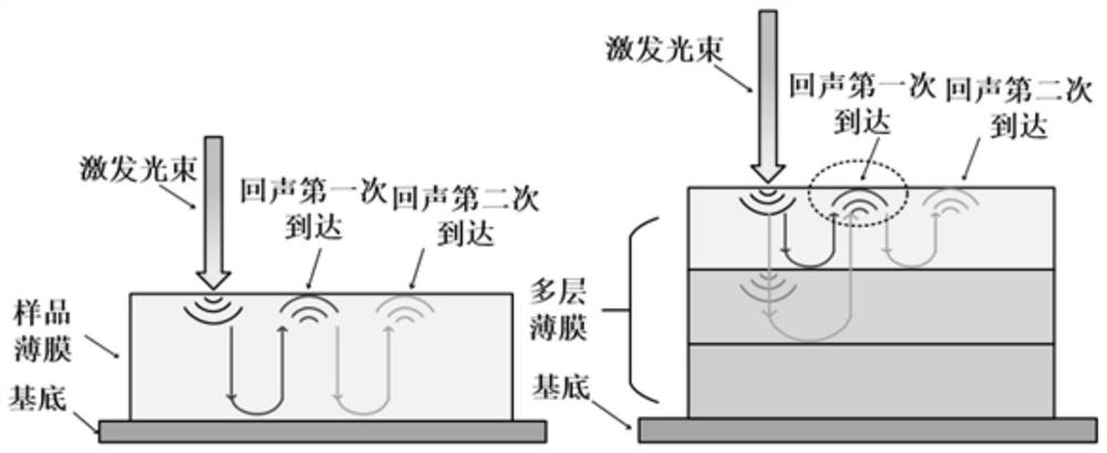
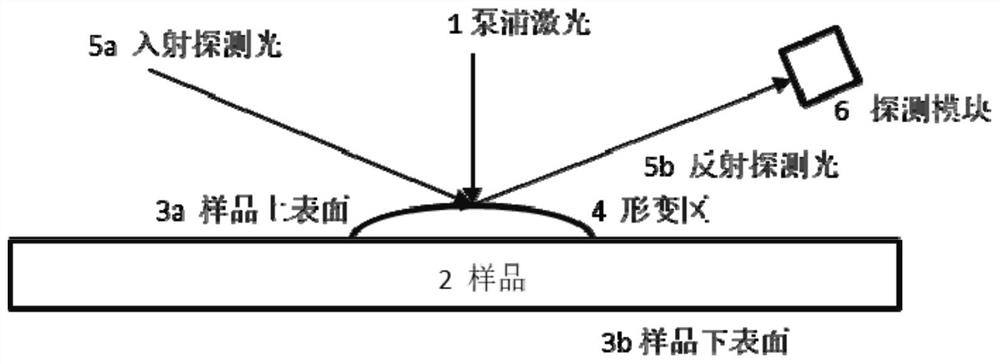
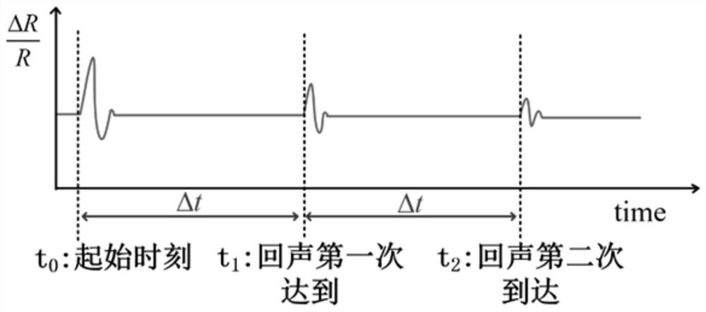
technical field [0001] The invention belongs to an acousto-optic measuring system and is mainly used for measuring metal films and dielectric films. Specifically, it relates to a device and method for detecting changes in reflected light. Background technique [0002] At present, the acousto-optic measurement in the prior art is mainly based on the following: the short-pulse laser is irradiated on the surface of the film sample, and the film 2 to be tested absorbs photons to generate thermoelastic deformation, forming a deformation zone on the surface; thermoelastic deformation generates sound waves that propagate on the solid surface and inside ; The longitudinal sound wave propagates to the interface (the junction of the substrate or the film and the film) to generate the first echo signal; the first echo signal reaches the upper surface, causing further changes in the deformation; the echo signal rebounds after hitting the upper surface , after the rebound hits the interf...

Claims


Application Information

Patent Timeline
Patent Type & Authority Applications(China)
IPC IPC(8): G01B11/06
CPCG01B11/06
Inventor 王奇李仲禹王政
Owner SHANGHAI PRECISION MEASUREMENT SEMICON TECH INC
Why Eureka
Try Eureka