Optical fiber mechanical property detection equipment
A technology of mechanical performance and testing equipment, applied in the field of communication, can solve the problems of single function and complicated operation of testing equipment, and achieve the effect of convenient adjustment
- Summary
- Abstract
- Description
- Claims
- Application Information
AI Technical Summary
Problems solved by technology
Method used
Image
Examples
specific Embodiment approach 1
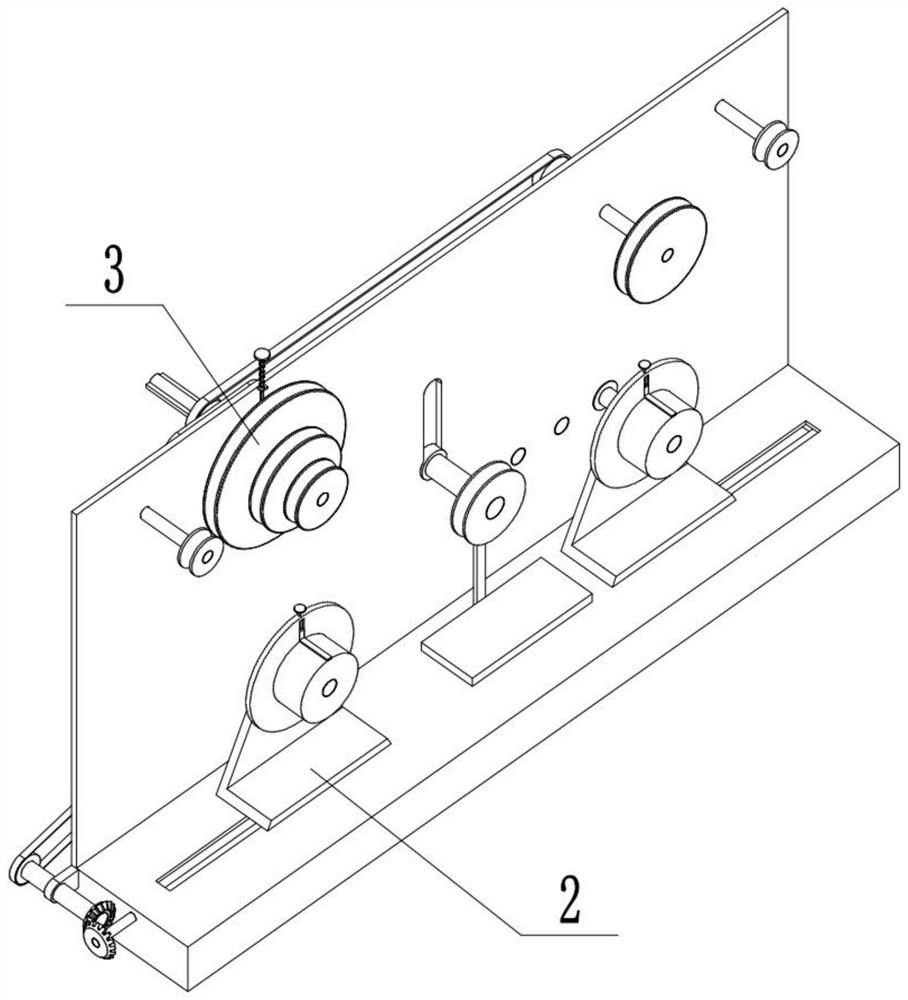
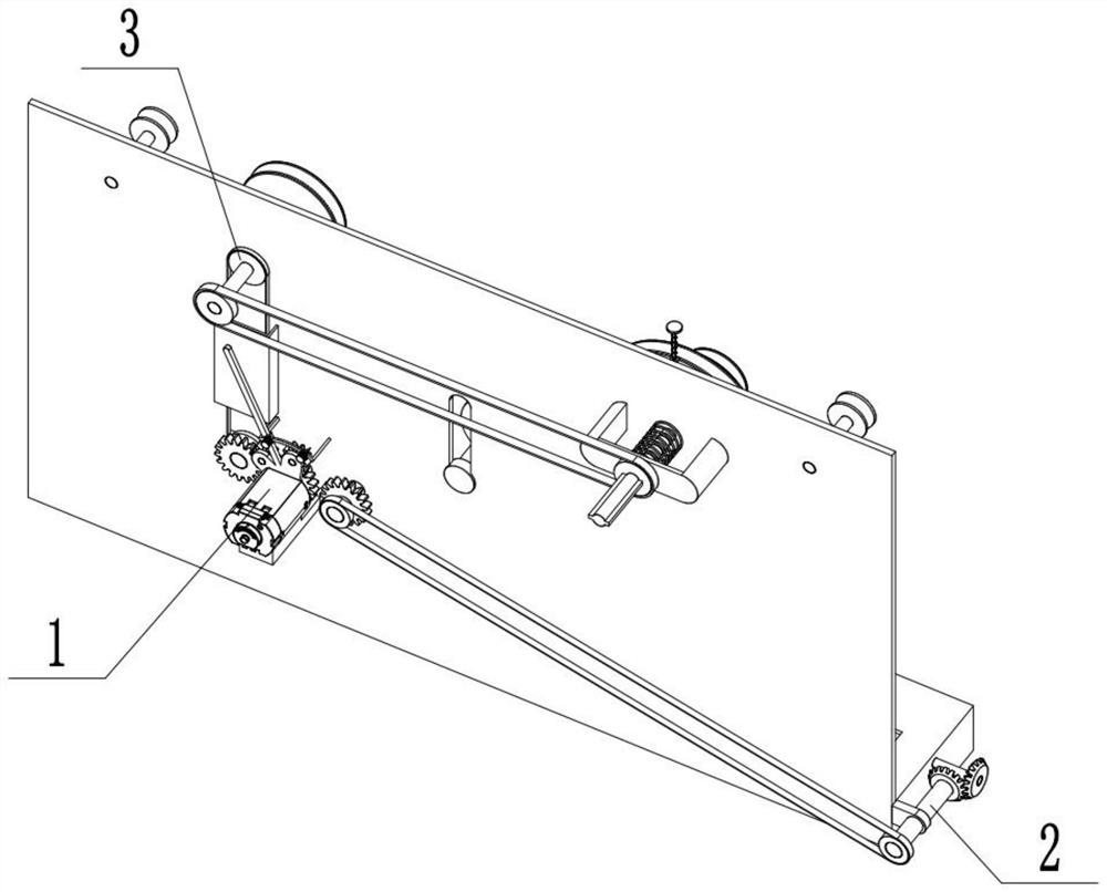
[0030] Combine below Figure 1-15 Describe this embodiment, an optical fiber mechanical performance testing device, including a power assembly 1, a tensile performance detection assembly 2 and a constant stress and constant axial strain screening assembly 3, the tensile performance detection assembly 2 and a constant The stress and constant axial strain screening assembly 3 is connected to the power assembly 1, and the tensile performance detection assembly 2 is connected to the constant stress and constant axial strain screening assembly 3.
specific Embodiment approach 2
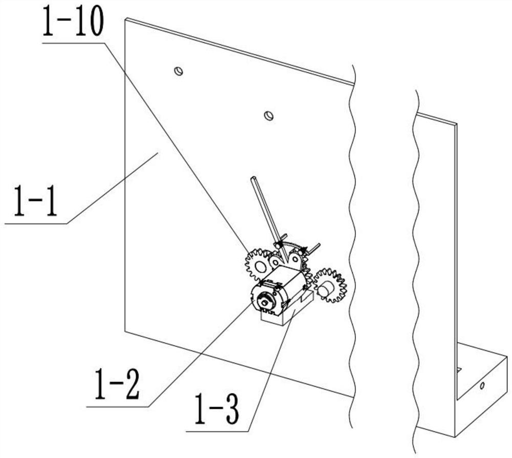
[0032] Combine below Figure 1-15 Describe this embodiment, this embodiment will further explain the first embodiment, the power assembly 1 includes a vertical plate 1-1, a motor 1-2, a motor bracket 1-3, a motor shaft 1-4, and a motor gear 1-5 , clutch bracket 1-6, clutch handle 1-7, clutch gear 1-8, clutch gear shaft 1-9, gear Ⅰ 1-10, gear Ⅱ 1-11, gear Ⅱ shaft 1-12, handle slide 1-13, Inclined block 1-14 and spring I 1-15, motor 1-2 is connected with motor bracket 1-3, motor bracket 1-3 is connected with vertical plate 1-1, motor 1-2 is connected with motor shaft 1-4 , the motor shaft 1-4 is connected with the motor gear 1-5, the motor shaft 1-4 is connected with the vertical plate 1-1 in rotation, the clutch bracket 1-6 is connected with the motor shaft 1-4 in rotation, and the clutch bracket 1-6 is connected with the clutch The handles 1-7 are connected, the clutch bracket 1-6 is rotationally connected with the two clutch gear shafts 1-9, the two clutch gear shafts 1-9 ar...
specific Embodiment approach 3
[0034] Combine below Figure 1-15 Describe this embodiment, this embodiment will further explain Embodiment 1, the tensile performance detection assembly 2 includes pulley I 2-1, belt I 2-2, pulley I shaft 2-3, pulley I shaft lug 2 -4, bevel gear Ⅰ2-5, bevel gear Ⅱ2-6, two-way threaded shaft 2-7, equipment base 2-8, threaded slider 2-9, slider chute 2-10, sliding bracket 2-11, volume Disc 2-12, reel 2-13, friction shaft 2-14, knob 2-15, clamping thread shaft 2-16, clamp 2-17 and rotating shaft 2-18, pulley Ⅰ2-1 has two , the two pulleys Ⅰ2-1 are respectively connected with the gear Ⅱ shaft 1-12 and the pulley Ⅰ shaft 2-3, the two pulleys Ⅰ2-1 are connected through the belt Ⅰ2-2, and the pulley Ⅰ shaft 2-3 is connected with The pulley I shaft lug 2-4 is rotationally connected, the pulley I shaft lug 2-4 is connected to the vertical plate 1-1, the pulley I shaft 2-3 is connected to the bevel gear I2-5, and the bevel gear I2- 5 is meshed with the bevel gear II 2-6, and the beve...
PUM
 Abstract
Description
Claims
Application Information
 - R&D
- Intellectual Property
- Life Sciences
- Materials
- Tech Scout
- Unparalleled Data Quality
- Higher Quality Content
- 60% Fewer Hallucinations
Browse by: Latest US Patents, China's latest patents, Technical Efficacy Thesaurus, Application Domain, Technology Topic, Popular Technical Reports.
© 2025 PatSnap. All rights reserved.Legal|Privacy policy|Modern Slavery Act Transparency Statement|Sitemap|About US| Contact US: help@patsnap.com


