

Illuminating device and projector
a technology of projector and illumination device, which is applied in the direction of lighting and heating apparatus, instruments, and lighting, etc., can solve the problems of reducing the efficiency of filtering, increasing manufacturing costs, and affecting the durability of projectors, so as to effectively cut off ultraviolet rays or infrared rays, prevent defects in the device to be illuminated or the optical elements, and improve the durability of the projector
- Summary
- Abstract
- Description
- Claims
- Application Information
AI Technical Summary
Benefits of technology
Problems solved by technology
Method used
Image

Examples
first embodiment
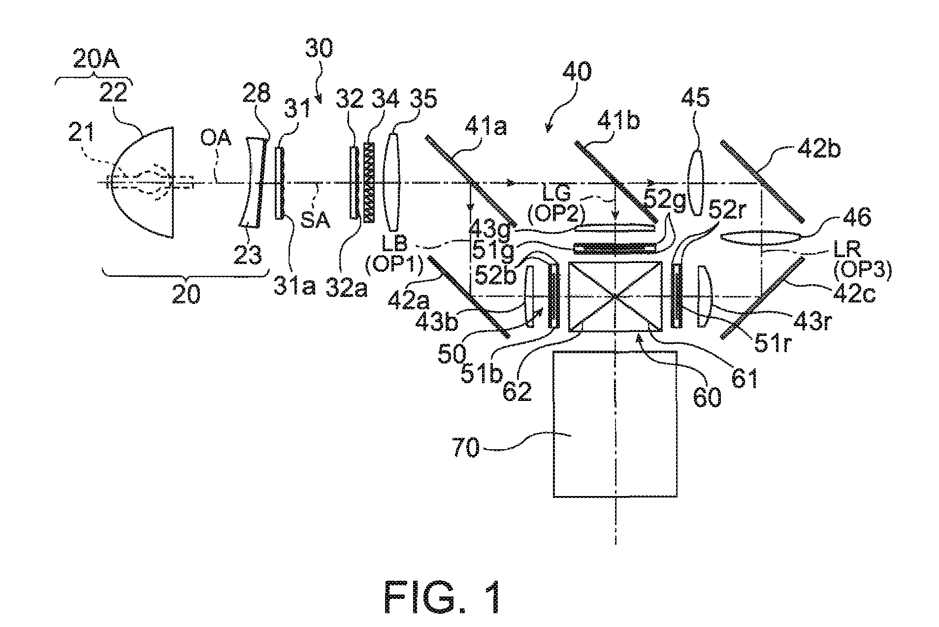
[0029]FIG. 1 is a block diagram illustrating the structure of an optical system of a projector according to a first embodiment of the invention.
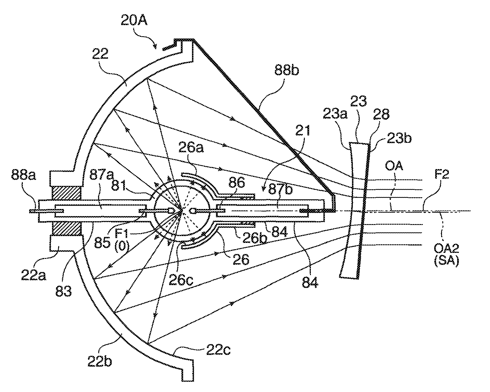
[0030]A projector 10 is an optical apparatus for modulating a light beam emitted from a light source on the basis of image information to form an optical image and for enlarging and projecting the optical image onto a screen. The projector 10 includes a light source lamp unit 20, an illumination optical system 30, a color separating device 40, a light modulating unit 50, a dichroic cross prism 60, and a projection optical system 70. The light source lamp unit 20 and the illumination optical system 30 constitute an illustrating device for emitting an illustration light for illuminating the light modulating device 50.
[0031]The light source lamp unit 20 condenses light beams radially emitted from a lamp body 21 to be incident on the light modulating unit 50 through the illumination optical system 30 and the color separating device 40. The light...
second embodiment
[0058]FIG. 5 is a side view illustrating a light source lamp unit 120 of an illuminating device according to a second embodiment of the invention. The light source lamp unit 120 is used for the projector 10 according to the first embodiment shown in FIG. 1 instead of the light source lamp unit 20. In the light source lamp unit, components not particularly described in this embodiment have the same structure as those in the light source lamp unit 20 according to the first embodiment. In addition, in this embodiment, the same components as those in the first embodiment have the same reference numerals, and thus a description thereof will be omitted.
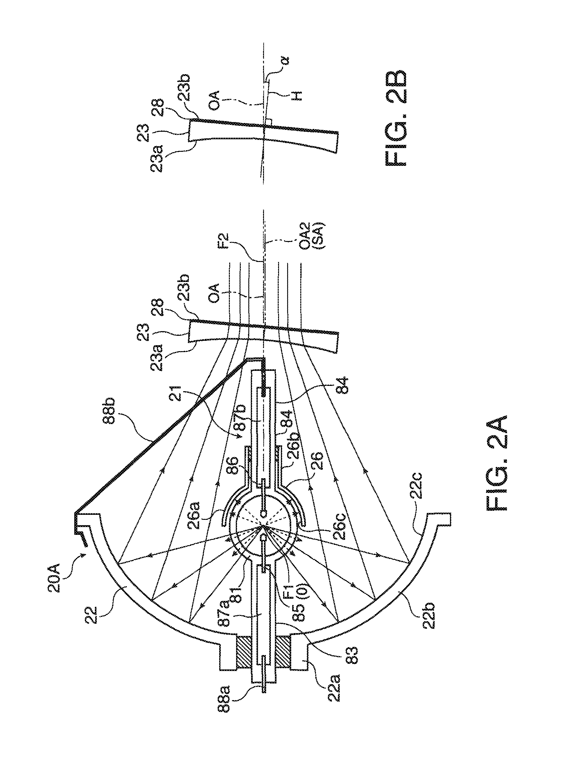
[0059]In the light source lamp unit 120 according to the second embodiment, a main reflecting mirror 122 has a paraboloid, not an ellipsoid. The main reflecting mirror 122 reflects light emitted from a lamp body (not shown) as parallel light. A plano-convex lens 123A and a plano-concave lens 123B are arranged in this order on the emission s...
third embodiment
[0061]In the second embodiment, the plano-convex lens 123A is provided orthogonal to the lamp axis OA, but the plano-concave lens 123B is inclined at a very small angle with respect to the lamp axis OA. However, the filter 28 may be formed on the planar surface of the plano-convex lens 123A, and the plano-convex lens 123A may be provided such that the normal line of the planar surface is inclined with respect to the lamp axis OA. In this embodiment, the above-mentioned structure will be described. FIG. 6 is a side view illustrating a light source lamp unit 220 of an illuminating device according to a third embodiment of the invention. In the light source lamp unit 220, components not particularly described in this embodiment have the same structure as those in the light source lamp unit 120 according to the second embodiment.
[0062]In the light source lamp unit 220 according to the third embodiment, a plano-convex lens 223A and a plano-concave lens 223B are arranged in this order on ...
PUM
 Abstract
Description
Claims
Application Information