
Optical component manufacturing method and pressing jig

A manufacturing method and technology of optical components, applied in optical components, coupling of optical waveguides, optics, etc., can solve the problems of individual poor loading quality, incorrect loading, etc., and achieve the effect of quality improvement

Pending Publication Date: 2021-06-29
SUMITOMO ELECTRIC IND LTD
View PDF7 Cites 0 Cited by
  • Summary
  • Abstract
  • Description
  • Claims
  • Application Information

AI Technical Summary

Problems solved by technology

Therefore, when loading is difficult as described above, there may be individual differences in the quality of loading.
In addition, there may be quality problems such as incorrect loading

Method used


Image

  • Optical component manufacturing method and pressing jig
  • Optical component manufacturing method and pressing jig
  • Optical component manufacturing method and pressing jig

Examples


Embodiment Construction

[0031] [Description of Embodiments of the Present Invention]

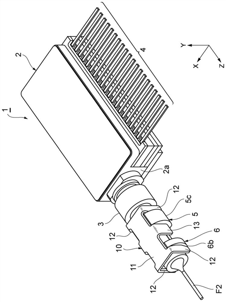
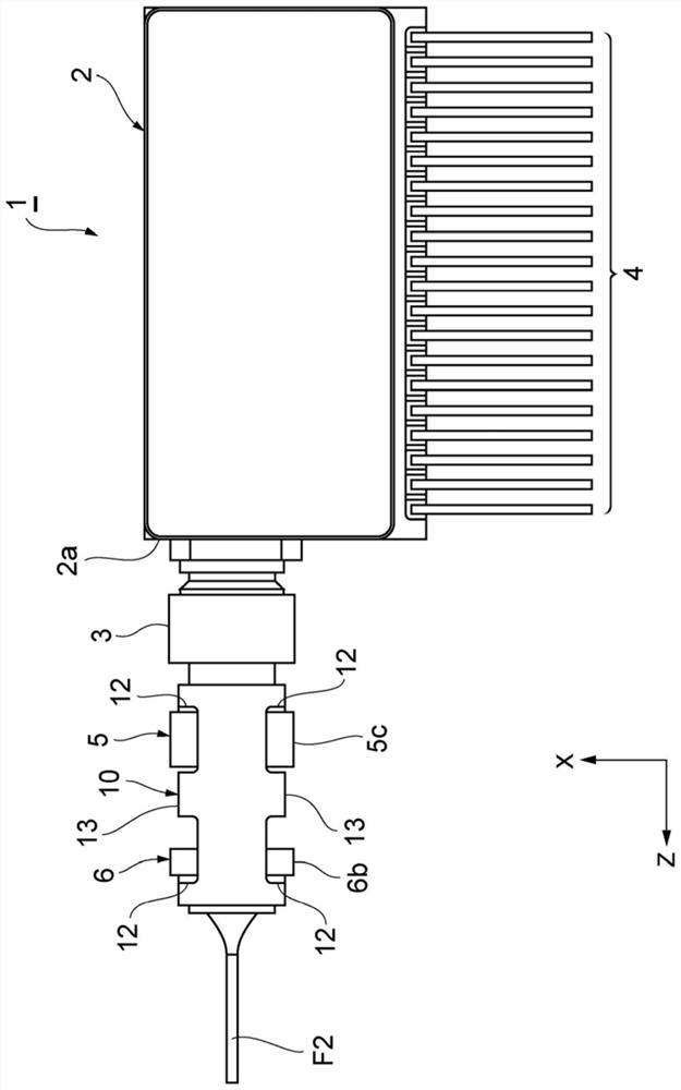
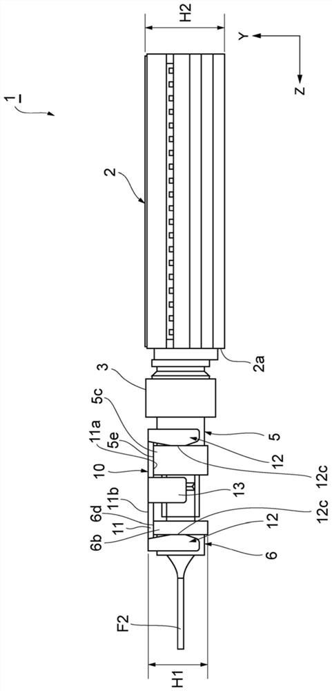
[0032] First, the contents of the embodiments of the present invention will be listed and described. A method of manufacturing an optical component according to an embodiment is a method of manufacturing an optical component including: an optical module having a cylindrical receptacle for holding a first optical fiber and having a A first flat surface parallel to the optical axis of the first optical fiber; a cylindrical optical fiber holding member, which holds a second optical fiber optically coupled with the first optical fiber, and has a surface parallel to the optical axis of the second optical fiber on the outer surface A second flat surface; and a clamping member, which has a third flat surface that determines the parallelism between the first flat surface and the second flat surface, and presses the receptacle and the optical fiber holding member against each other, and the manufacturing method of the optic...


PUM


Abstract

The invention provides an optical component manufacturing method and a pressing jig which can standardize loading work and improve quality. The optical component manufacturing method according to one embodiment includes: a step for attaching a clamp member (10) to a receptacle (5) and a plug (6) of an optical module; and a step of pressing the socket (5) and the plug (6) of the optical module from the lower side and pressing the clamp member (10) from the upper side, in the pressing step, using a jig having a pressing part (60) having a lower surface (66) for pressing the flat surface (5e) of the socket (5) and the flat surface (6d) of the plug (6) with varying parallelism, wherein the pressing is performed until the degree of parallelism between the flat surface (5e) of the socket (5) and the flat surface (6d) of the plug (6) is determined by a contact surface (11a) of the clamp member (10).

Description

technical field [0001] The present invention relates to a method of manufacturing an optical component and a pressing jig. Background technique [0002] Patent Document 1 describes an optical connector to which an optical cable is connected. In the optical connector, a receptacle of an optical device mounted on the surface of a printed board and a ferrule mounted on a free end of an optical fiber are butted against each other and inserted into a ferrule. In an optical connector, a receptacle of an optical device and a free end of an optical fiber are joined to each other by a clamp. [0003] Patent Document 1: Japanese Patent Application Laid-Open No. 7-318755 [0004] As mentioned above, in the optical connector, the receptacle of the optical device and the ferrule loaded on the free end of the optical fiber are inserted into the sleeve in a state of butting with each other, and the receptacle of the optical device and the free end of the optical fiber are connected to ea...

Claims


Application Information

Patent Timeline
IPC IPC(8): G02B6/42
CPCG02B6/424G02B6/4228G02B6/3898G02B6/3873G02B6/389G02B6/3825G02B6/4292G02B6/4236G02B6/3802G02B6/3893
Inventor 铃木三千男佐伯智哉藤村康
Owner SUMITOMO ELECTRIC IND LTD
Learn More