Reflector antenna assembly with flat-top directional diagram

A technology of antenna components and reflectors, which is applied to antennas, folding antennas, antenna supports/mounting devices, etc., can solve the problems of reducing antenna precision, increasing the difficulty of antenna component debugging, complex structure, etc., and achieve the effect of reducing complexity

Active Publication Date: 2021-06-29
XIAN HENGDA MICROWAVE TECH DEV
View PDF11 Cites 0 Cited by
  • Summary
  • Abstract
  • Description
  • Claims
  • Application Information

AI Technical Summary

Problems solved by technology

[0003]Common reflector antenna components are usually complex in structure and require a large number of parts for assembly. However, the signal transmission and reception accuracy of an

Method used


Image

  • Reflector antenna assembly with flat-top directional diagram
  • Reflector antenna assembly with flat-top directional diagram
  • Reflector antenna assembly with flat-top directional diagram

Examples


Embodiment Construction

[0028] The present invention will be described in detail below in conjunction with the accompanying drawings and specific embodiments.

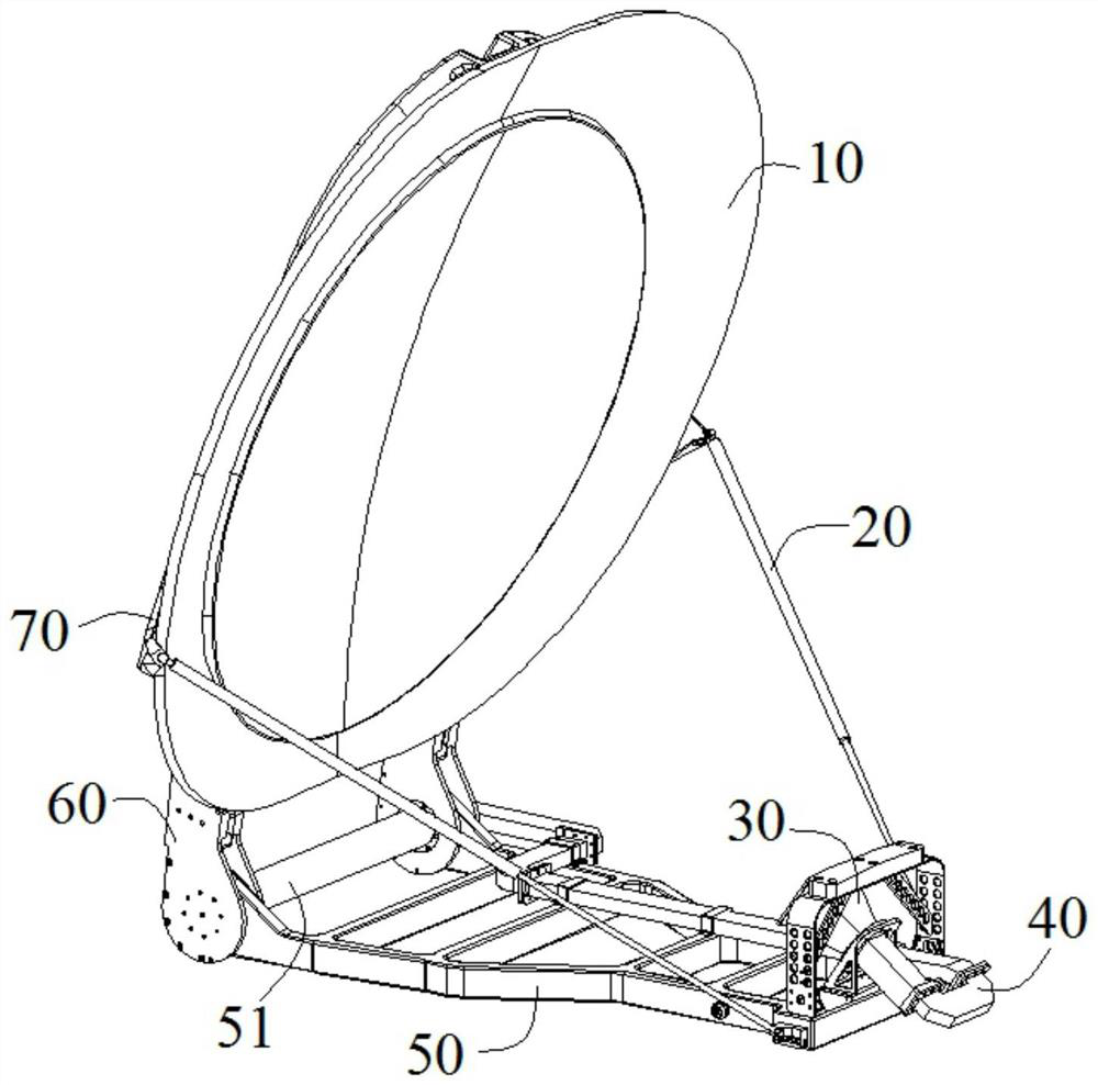
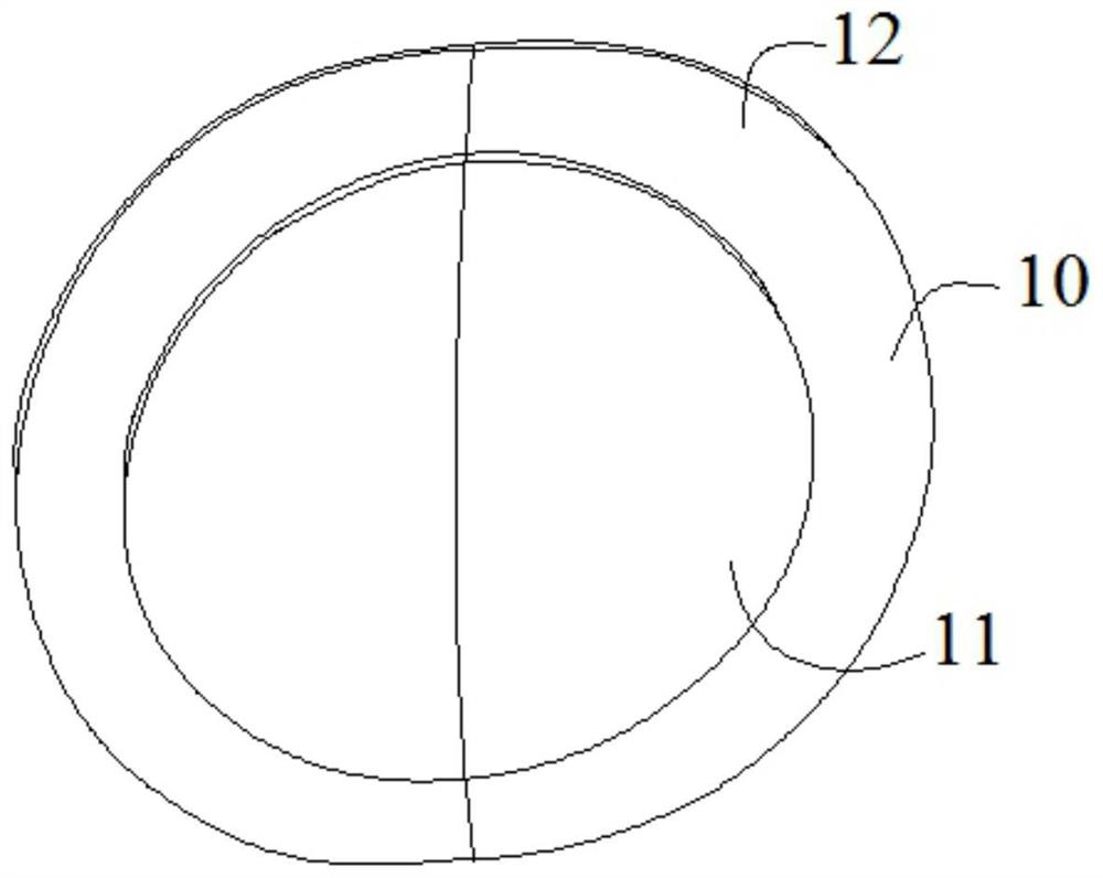
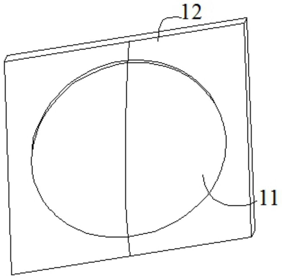
[0029] An embodiment of the present invention discloses a reflector antenna assembly with a flat-top pattern, including a reflector antenna, such as figure 2 As shown, the front of the reflector antenna is a reflector 10, and the reflector 10 is a parabola, and the parabola includes a central reflection area 11 and an edge reflection area 12; the center reflection area 11 is circular, the edge reflection area 12 is a ring, and the edge reflection area 12 The inner circumference is connected to the outer circumference of the central reflection area 11; there is a depth difference at the edge of the connection between the central reflection area 11 and the edge reflection area 12, and the depth difference is used to make the reflection surface 10 form a beam with a flat-top pattern.

[0030] Such as figure 1 As shown, the bottom of the reflec...


PUM


Abstract

The invention discloses a reflector antenna assembly with a flat-top directional diagram, the front surface of a reflector antenna is a reflector, the reflector is a paraboloid, and the paraboloid comprises a central reflection area and an edge reflection area; the central reflection area is circular, the edge reflection area is annular, and the inner periphery of the edge reflection area is connected with the outer periphery of the central reflection area; the connecting edge of the central reflection area and the edge reflection area has a depth difference, and the depth difference is used for enabling the reflection surface to form a wave beam with a flat-top directional diagram; the antenna assembly can be formed through a small number of parts, the complexity of the antenna assembly and the debugging difficulty of the antenna assembly can be reduced, the reflecting surface of the paraboloid-shaped reflecting surface antenna is divided into the central reflecting area and the edge reflecting area, the surface of the central reflecting area and the surface of the edge reflecting area have the depth difference, a wave beam with a flat-topped pattern characteristic can be formed through the reflector antenna, and multiple satellites can be tracked at the same time.

Description

technical field [0001] The invention belongs to the technical field of reflector antennas, in particular to a reflector antenna assembly with a flat-top pattern. Background technique [0002] The reflective surface antenna assembly is an antenna that uses various components and a metal reflective surface to form a predetermined beam. The gain is generally higher than that of a wire antenna, and the higher the operating frequency and the larger the aperture size of the reflector, the higher the gain of the antenna. It is widely used in satellite communication, microwave communication, radar, remote sensing, and bioelectronic technology. [0003] Common reflector antenna assemblies are usually complex in structure and require a large number of parts for assembly, while the signal receiving and receiving accuracy of the antenna assembly is often affected by assembly, and the increase in the number of parts may reduce the antenna accuracy and increase the difficulty of debuggin...

Claims


Application Information

Patent Timeline
IPC IPC(8): H01Q15/16H01Q1/10H01Q1/50H01Q3/02H01Q1/12
CPCH01Q15/16H01Q1/10H01Q1/50H01Q3/02H01Q1/12
Inventor 伍捍东王英英刘迎喜于通尹国选罗松
Owner XIAN HENGDA MICROWAVE TECH DEV
Why Eureka
Try Eureka