Movable lifting medical infusion support
An infusion stand and medical technology, applied in the field of infusion stand, can solve the problems of single fixation, large volume of liquid medicine bottle, affecting infusion efficiency, etc., and achieve the effect of avoiding being unable to be limited.
- Summary
- Abstract
- Description
- Claims
- Application Information
AI Technical Summary
Problems solved by technology
Method used
Image
Examples
Embodiment 1
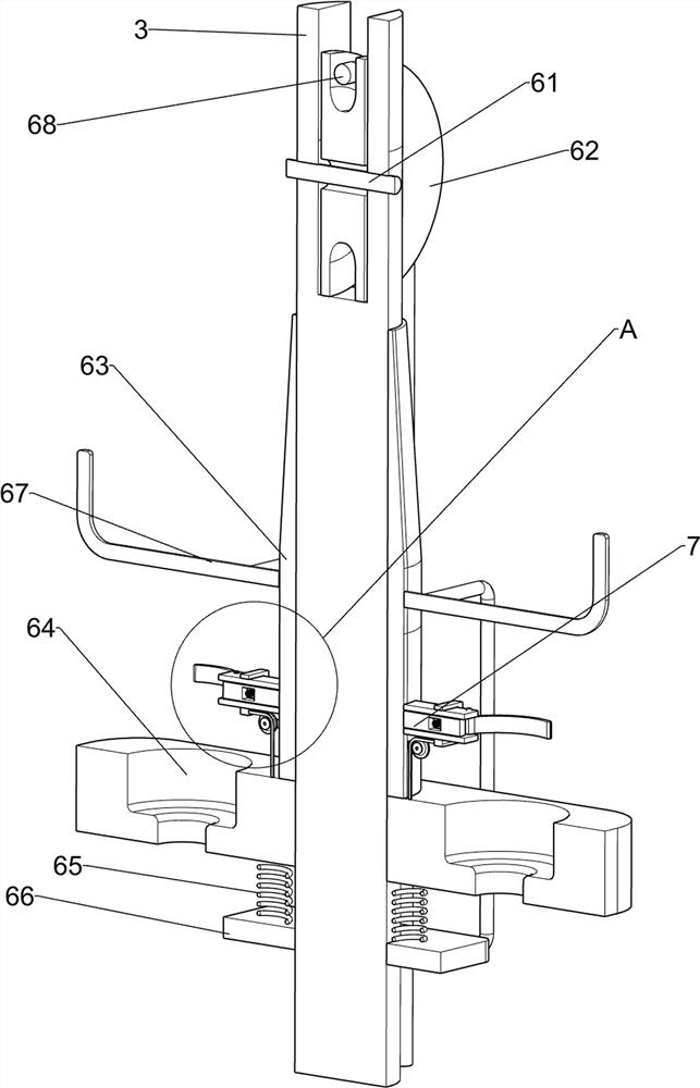
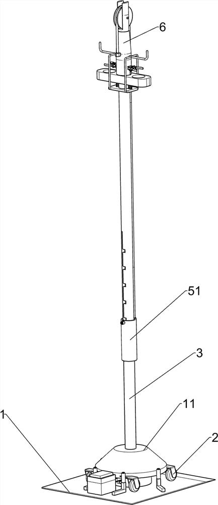
[0029] A movable lift medical infusion stand, such as Figure 1-Figure 3 As shown, it includes a bottom plate 1, a chassis 11, a wheel 2, a vertical rod 3, a weight 4, a transmission device 5 and a lifting device 6. The top of the bottom plate 1 is rotatably placed with four wheels 2, and between the four wheels 2 is arranged There is a chassis 11, a vertical rod 3 is fixed in the middle of the top of the chassis 11, a weight 4 is fixed in the middle of the top of the bottom plate 1, a transmission device 5 is arranged on the vertical rod 3, the transmission device 5 cooperates with the weight 4, and the vertical rod 3 is connected with the transmission A lifting device 6 is provided between the devices 5 .
[0030] The transmission device 5 includes a sliding handle 51, a clamping block 54 and a sliding rod 55. The middle of the vertical rod 3 is circumferentially slidably sleeved with a sliding handle 51; The middle part is evenly spaced with card slots 53 , the left and ri...
Embodiment 2
[0034] On the basis of Example 1, as figure 2 , Figure 5 , Image 6 and Figure 7 As shown, a fixing device 7 is also included. The fixing device 7 includes a fixing plate 71 , a caliper 72 , a second rotating shaft 73 , a second spring 74 , a sliding frame 75 , a third rotating shaft 76 , a guide wheel 77 and a second pulling rope 78 , the lower part of the lifting sleeve 63 is fixed with a fixed plate 71 on both the front and rear sides. The fixed plate 71 is provided with a second rotating shaft 73 rotatably outside. A second spring 74 is fixedly connected between the inside of the fixing plate 71. A sliding frame 75 is slidably sleeved on the upper part of the fixing plate 71. 76. A guide wheel 77 is fixed circumferentially in the middle of the third rotating shaft 76, and a second pull rope 78 is fixed in the middle of the lower part of the inner side of the sliding frame 75. Fixed connection.
[0035]It also includes a locking device 8. The locking device 8 includ...
Embodiment 3
[0039] On the basis of Example 1 and Example 2, as figure 2 , Figure 5 , Figure 8 and Figure 9 As shown, a positioning device 9 is also included. The positioning device 9 includes a fixing rod 91 and a rubber wheel 92. Four fixing rods 91 are fixed at intervals on the left side of the top of the bottom plate 1. The outer top of the fixing rod 91 is rotatably provided with a rubber wheel 92. .
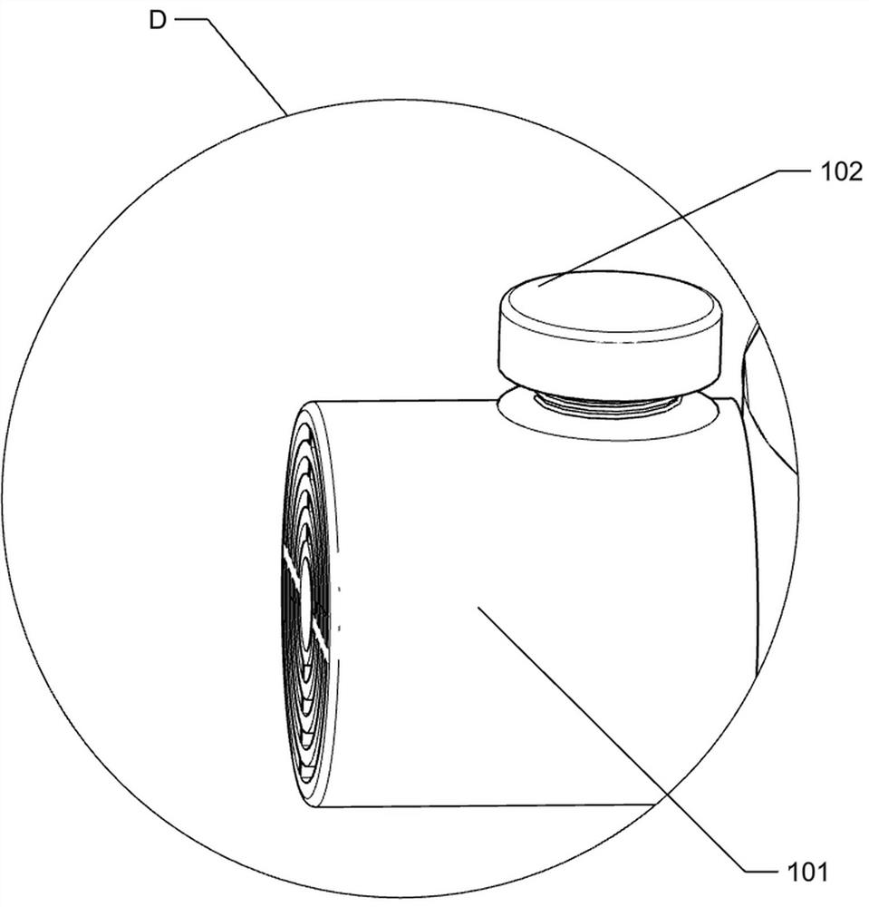
[0040] It also includes a calling device 10 , the calling device 10 includes a buzzer 101 and a button 102 , a buzzer 101 is provided on the upper left side of the sliding handle 51 , and a button 102 is provided on the buzzer 101 .
[0041] After the patient goes to the toilet, the rubber wheel 92 plays a guiding role, which is convenient for people to move the device to the top of the weight 4, so that people can avoid moving the device out of place.
[0042] When the patient encounters an emergency, the buzzer 101 can be operated to generate a sound through the button 102, so...
PUM
 Abstract
Description
Claims
Application Information
 - R&D
- Intellectual Property
- Life Sciences
- Materials
- Tech Scout
- Unparalleled Data Quality
- Higher Quality Content
- 60% Fewer Hallucinations
Browse by: Latest US Patents, China's latest patents, Technical Efficacy Thesaurus, Application Domain, Technology Topic, Popular Technical Reports.
© 2025 PatSnap. All rights reserved.Legal|Privacy policy|Modern Slavery Act Transparency Statement|Sitemap|About US| Contact US: help@patsnap.com


