Emergency department disinfectant uninterrupted mixing equipment
A technology of mixing equipment and disinfectant, which is applied in the direction of mixers, fluid mixers, mixers with rotating stirring devices, etc., can solve the problems of single function and uneven disinfectant, and achieve the effect of high uniformity of finished products
- Summary
- Abstract
- Description
- Claims
- Application Information
AI Technical Summary
Problems solved by technology
Method used
Image

Examples
specific Embodiment approach 1
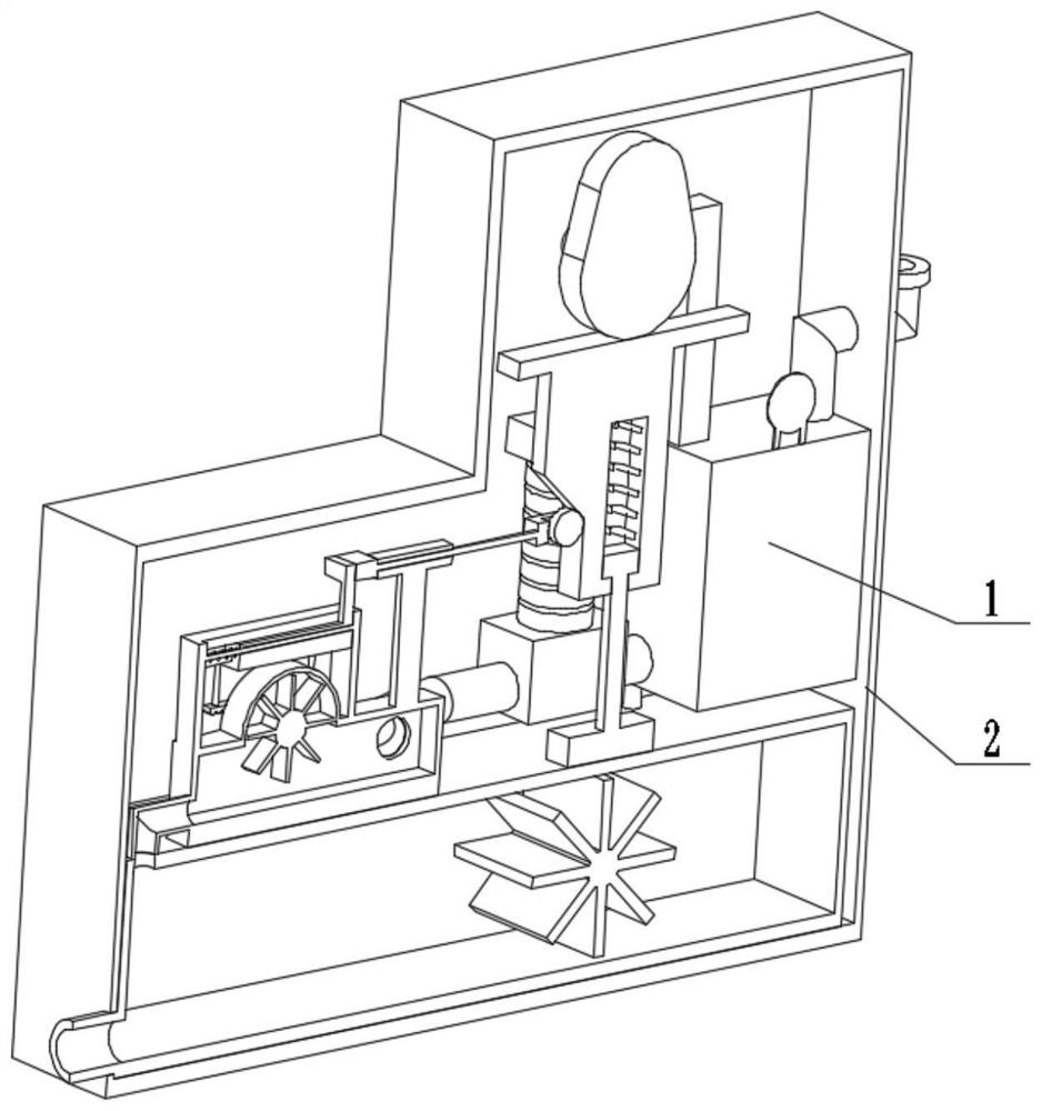
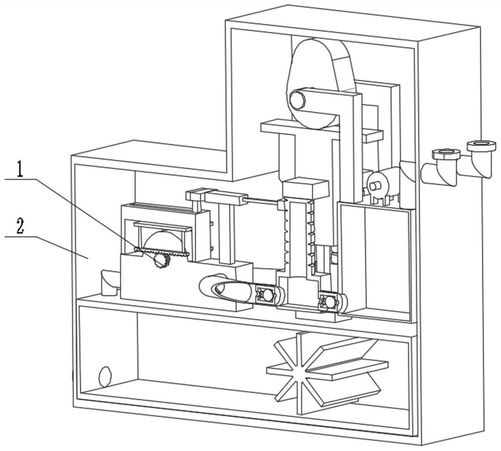
[0026] Combine below figure 1 , figure 2 , image 3 , Figure 4 , Figure 5 , Figure 6 , Figure 7 , Figure 8 , Figure 9 , Figure 10 , Figure 11 Describe this embodiment, the present invention relates to a kind of mixing equipment, more specifically a kind of equipment for discontinuous mixing of disinfectant solution in emergency department, including mixing actuator 1 and casing mechanism 2, the equipment can add stock solution and complete pre-mixing, the equipment It can carry out countercurrent stirring while spraying pre-mixing. When the equipment finishes spraying, the mixed disinfectant is accelerated and discharged into the finished product box. The equipment can use the same power to complete the activation of the finished product, and the output of the finished product has high uniformity.
[0027] The mixing actuator 1 is connected with the casing mechanism 2 .
specific Embodiment approach 2
[0029] Combine below figure 1 , figure 2 , image 3 , Figure 4 , Figure 5 , Figure 6 , Figure 7 , Figure 8 , Figure 9 , Figure 10 , Figure 11Describe this embodiment, this embodiment will further explain the first embodiment, the mixing actuator 1 includes a disinfection liquid outlet pipe 1-1, a finished product box 1-2, a connecting elbow 1-3, a mixing box 1-4, Gear 1-5, rack 1-6, rack frame 1-7, chute 1-8, connecting seat 1-9, limit support frame 1-10, pulley seat with square column 1-11, pulley 1- 12. Seat with inclined plane 1-13, sliding fit seat 1-14, cam with shaft 1-15, pulley 1-16, belt 1-17, belt I1-18, pulley I1-19, stock solution elbow with flange 1 -20, motor 1-21, pulley II1-22, stock solution tank with bearing seat 1-23, air bag 1-24, connecting pipe 1-25, pressure box 1-26, ejection pipe 1-27, pulley III1-28 , reciprocating rotating wheel with shaft 1-29, light hole 1-30, limit rod 1-31, spring 1-32, square hole 1-33, stepped square column ...
specific Embodiment approach 3
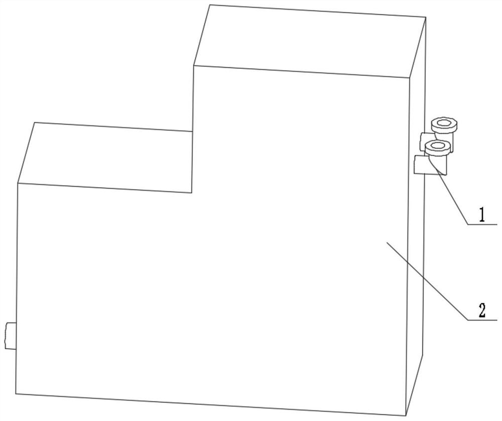
[0031] Combine below figure 1 , figure 2 , image 3 , Figure 4 , Figure 5 , Figure 6 , Figure 7 , Figure 8 , Figure 9 , Figure 10 , Figure 11 This embodiment will be described. This embodiment will further explain the first embodiment. The casing mechanism 2 includes a piercing hole 2-1, a casing body 2-2, a piercing hole 2-3, and a piercing hole 2-1. Both are arranged on the casing body 2-2 with the penetration hole 2-3, the casing body 2-2 is connected with the finished product case 1-2, and the disinfection liquid outlet pipe 1-1 passes through the penetration hole 2-1, with The flange stock solution elbow 1-20 penetrates into the casing body 2-2 from the penetration hole 2-3, and the casing body 2-2 plays the role of dustproof protection.
PUM
 Abstract
Description
Claims
Application Information
 - R&D Engineer
- R&D Manager
- IP Professional
- Industry Leading Data Capabilities
- Powerful AI technology
- Patent DNA Extraction
Browse by: Latest US Patents, China's latest patents, Technical Efficacy Thesaurus, Application Domain, Technology Topic.
© 2024 PatSnap. All rights reserved.Legal|Privacy policy|Modern Slavery Act Transparency Statement|Sitemap