Tool for repairing flow passage of axial flow casing of aero-engine and application method for tool

An aero-engine and axial-flow technology, applied in the direction of injection devices, etc., can solve the problems affecting the performance parameters of the compressor and the out-of-tolerance of the inner flow path, etc., to achieve the effect of ensuring implementability, easy assembly, and improving spraying efficiency

Active Publication Date: 2021-07-02
CHINA HANGFA CHANGZHOU LANXIANG MACHINERY CO LTD
View PDF7 Cites 3 Cited by
  • Summary
  • Abstract
  • Description
  • Claims
  • Application Information

AI Technical Summary

Problems solved by technology

In actual processing, due to factors such as processing errors and deformation of thin-walled parts, the inner runner is out of tolerance. After scanning and measuring the runner of the casing assembly, it is found that the overall size of the runner deviates from the theoretical value by about 0.15~ 0.20mm, the outward expansion of the overall flow channel deviates from the theoretical value, which greatly affects the performance parameters of the compressor

Method used


Image

  • Tool for repairing flow passage of axial flow casing of aero-engine and application method for tool
  • Tool for repairing flow passage of axial flow casing of aero-engine and application method for tool

Examples


Embodiment 1

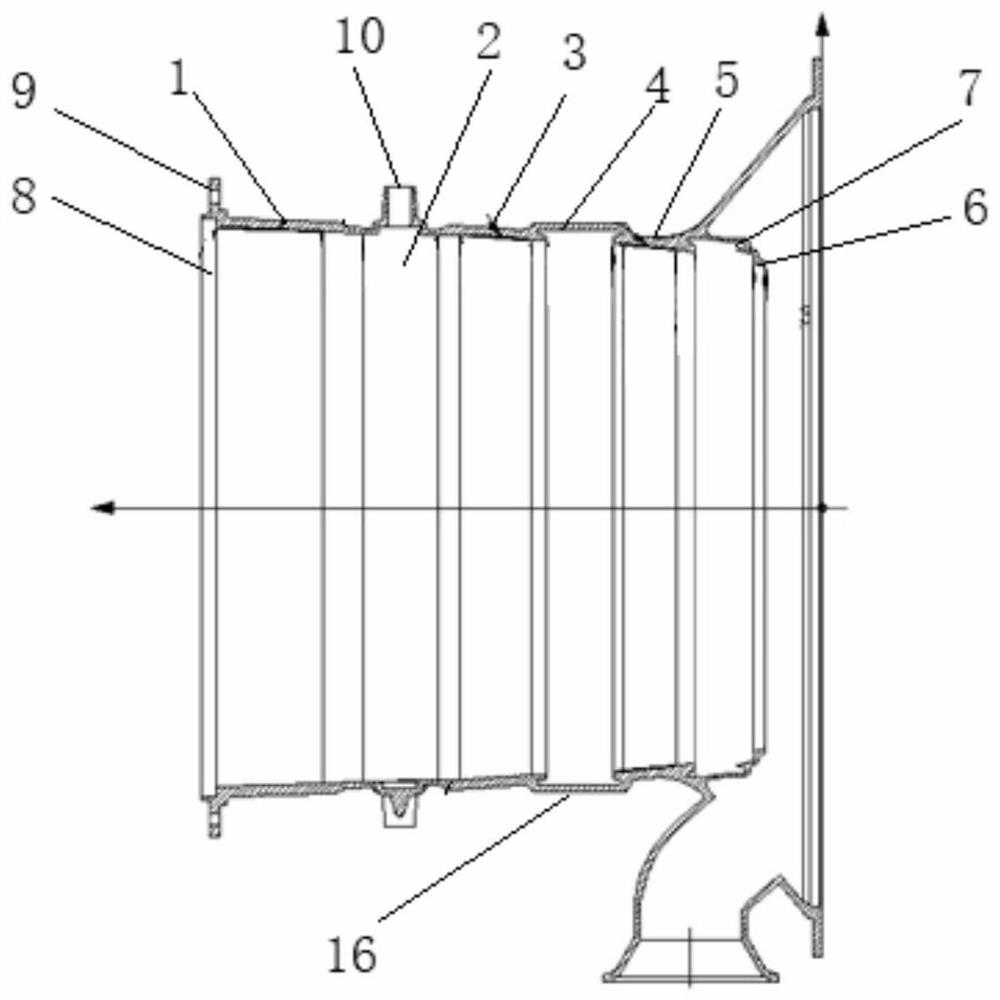
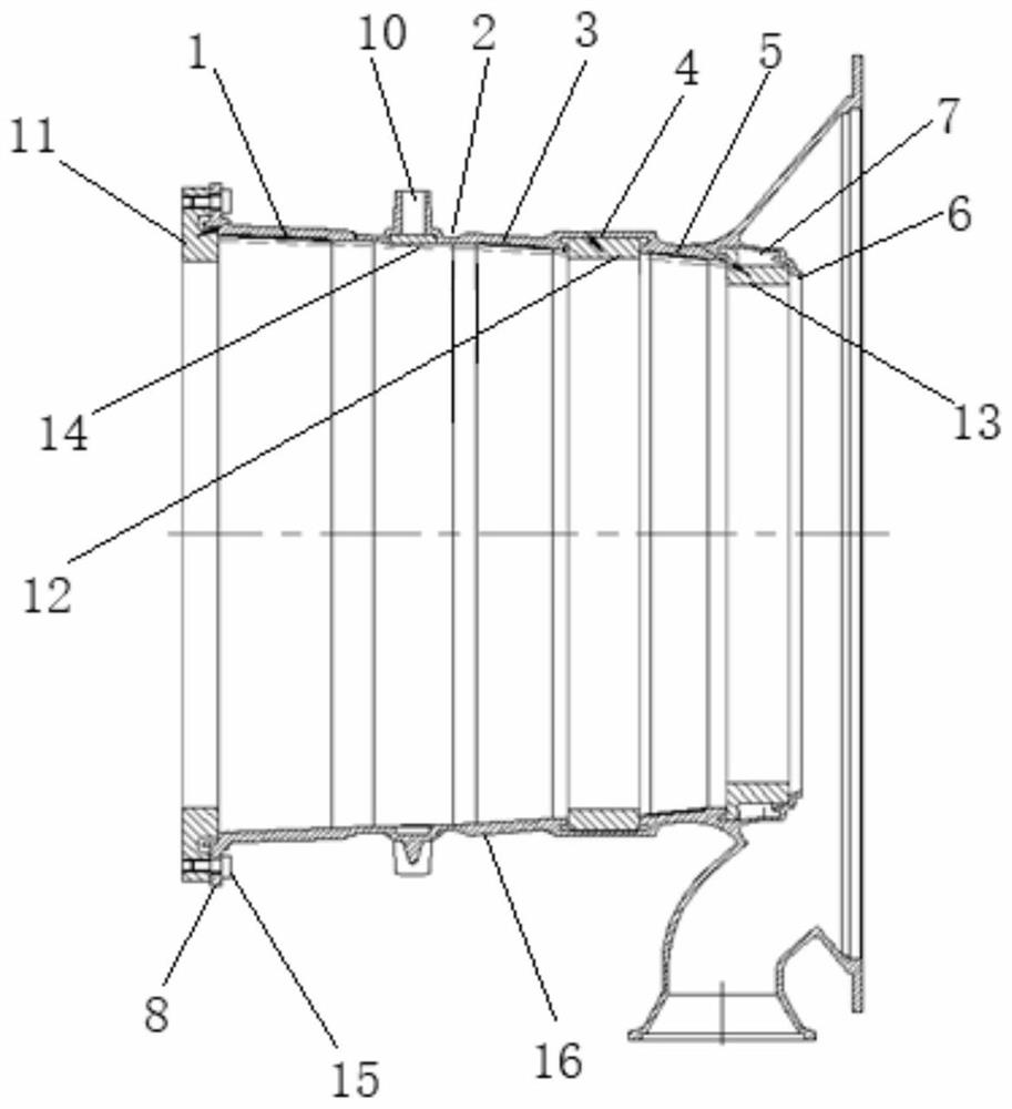
[0015] Such as Figure 1 to Figure 2 As shown, the tooling for repairing the flow path of the aero-engine axial flow casing in this embodiment includes the first protective ring 12 matching with the second-stage vane installation groove 4, and the first protection ring 12 matching with the third-stage vane installation groove 7. Two protective rings 13, spigot protective rings 11 and 30 plugs 14 that are compatible with the vane installation holes 10. The first protective ring 12 is composed of two first half-rings spliced ​​together. The second protective ring 13 It is composed of two second half-rings spliced ​​together; the outer wall of the first protection ring 12 fits with the inner wall of the second-stage stator vane installation groove 4 with a small gap, and the gap is less than 2.0mm; the outer wall of the second protection ring 13 and the third-stage stator vane The inner wall of the installation groove 7 fits with a small gap, and the gap is less than 2.0mm. The m...

Embodiment 2

[0018] The method of using the tooling for repairing the flow path of an aero-engine axial-flow casing includes the following steps: first, snap two first semi-annular bodies into the installation groove 4 of the second-stage vane, and connect the first semi-annular body with the second-stage vane Fill and apply 703 glue between the installation grooves 4, and form a circular first protective ring 12 from the first half ring body, snap the two second half ring bodies into the three-stage vane installation groove 7, and place them on the second half ring body. Fill and apply 703 glue between the ring body and the third-stage stationary vane installation groove 7, and form a circular second protective ring from the second half-annular body, and the outer wall of the second protective ring 13 and the third-stage stationary vane installation groove 7 The gap between the inner walls, the outer wall of the first protective ring 12 and the inner wall of the second-stage stationary van...


PUM


Abstract

The invention relates to a tool for repairing a flow passage of an axial flow casing of an aero-engine and an application method for the tool. The tool for repairing the flow passage of the axial flow casing of the aero-engine comprises a first protection ring, a second protection ring, a spigot protection ring and a plurality of plugs, wherein the first protection ring is matched with a second-stage stationary blade mounting groove, the second protection ring is matched with a third-stage stationary blade mounting groove, and the multiple plugs are matched with stationary blade mounting holes; the outer wall of the first protection ring is in small clearance fit with the inner wall of the second-stage stationary blade mounting groove; the outer wall of the second protection ring is in small clearance fit with the inner wall of the third-stage stationary blade mounting groove; the spigot protection ring sleeves a left-end spigot of the axial flow casing; during assembling, the first protection ring and the inner wall of the second-stage stationary blade mounting groove as well as the second protection ring and the inner wall of the third-stage stationary blade mounting groove are glued and fixed through glue; and the plugs and the stationary blade mounting holes are glued and fixed through glue.

Description

technical field [0001] The invention relates to the technical field of aero-engine repair auxiliary equipment, in particular to a tool for repairing an aero-engine axial-flow case flow channel and a method for using the same. Background technique [0002] A certain type of aero-engine axial-flow casing is a half-type structure, and the blank is made of integral castings. Its structure is as follows figure 1 As shown, after installation, the first inner runner 1, the second inner runner 2, the third inner runner 3, and the fourth inner runner 5 with different inner diameters are formed, wherein the second inner runner 2 is provided with multiple A vane installation hole 10, a T-shaped secondary vane installation groove 4 is formed between the third inner flow channel 3 and the fourth inner flow channel 5, and a T-shaped is formed between the fourth inner flow channel 5 and the tail end 6. The three-stage stationary vane installation groove 7 of the three-stage vane, and the ...

Claims


Application Information

Patent Timeline
Patent Type & Authority Applications(China)
IPC IPC(8): B05B13/02
CPCB05B13/02
Inventor 顾建刚
Owner CHINA HANGFA CHANGZHOU LANXIANG MACHINERY CO LTD
Why Eureka
Try Eureka