Building formwork connecting structure for civil engineering

A technology of building formwork and civil engineering, which is applied in the direction of building construction, formwork/formwork/work frame connectors, construction components on-site preparation, etc., which can solve the inconvenience of connection, affect the effect of concrete pouring, and the spacing of building formwork Difficult to adjust and other issues

Active Publication Date: 2021-07-02
中建三局科创产业发展有限公司
View PDF5 Cites 4 Cited by
  • Summary
  • Abstract
  • Description
  • Claims
  • Application Information

AI Technical Summary

Problems solved by technology

[0003] When the current building formwork is used, it is often necessary to splice multiple building formwork together. At this time, it is often necessary to use specific tools for connection, which is inconvenient to connect, and the distance between building formwork is not easy to adjust, which greatly affects Effects of pouring concrete

Method used


Image

  • Building formwork connecting structure for civil engineering
  • Building formwork connecting structure for civil engineering
  • Building formwork connecting structure for civil engineering

Examples


Embodiment 1

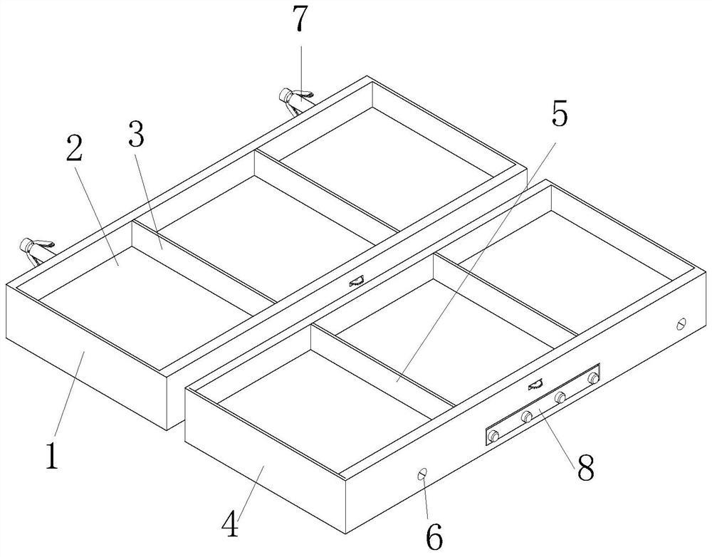
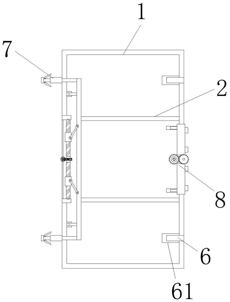
[0034] see figure 1 with figure 2 , the present invention provides a building formwork connection structure for civil engineering through improvement, including a first formwork body 1, a pouring groove 2, a first partition 3, a second formwork body 4, a second partition 5, and a slot 6 1. Connect the limiting mechanism 7 and the spacer supporting mechanism 8, the first formwork body 1 is provided with pouring grooves 2 inside, the pouring groove 2 is equidistantly distributed with first partitions 3, and the connecting limiting mechanism 7 is installed and fixed on the first formwork On the inner side of the left end of the body 1, the spacer support mechanism 8 is embedded and installed on the inner side of the right end of the second formwork body 4, the right end of the first formwork body 1 is provided with a second formwork body 4, and the second formwork body 4 is equidistantly distributed with second partitions 5 , slots 6 are provided on the front and rear sides of ...

Embodiment 2

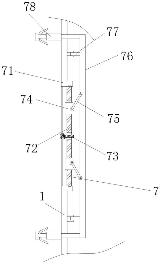
[0041] The present invention provides a building formwork connection structure for civil engineering through improvement. There are two limit rods 783, and damping hinges 7831 are arranged on the upper ends of the limit rods 783, which is beneficial to reset the limit rods 783. There are two sliders 74, and the sliders 74 are arranged oppositely along the front and rear sides of the screw rod 72. The upper ends of the two sliders 74 are provided with a swing rod 75, which is beneficial to push the push rod 76 to the right. Function, the slot 6 is provided with a card slot 61 inside.

[0042] The present invention provides a building formwork connection structure for civil engineering through improvement, and its working principle is as follows;

[0043] First, before use, the building formwork connection structure for civil engineering is placed horizontally, so that the first formwork body 1 and the second formwork body 4 support and fix the connection structure;

[0044] Se...


PUM


Abstract

The invention discloses a building formwork connecting structure for civil engineering. The building formwork connecting structure comprises a first formwork body, a pouring groove, a first partition, a second formwork body, a second partition, a slot, a connecting limiting mechanism and an interval jacking mechanism. According to the building formwork connecting structure, the connecting limiting mechanism is arranged on the left end of the first formwork body, a jacking block and a sliding rod are embedded into the inner side of the slot, after the jacking block is embedded into the inner side of a limiting groove, a limiting rod and the limiting groove are buckled with each other, then the sliding rod is driven to move to the right end by a push rod, and the limiting rod is tightly attached to the inner wall of the limiting groove, so that the advantage that the first formwork body and the second formwork body can be rapidly connected with each other is achieved; and the interval jacking mechanism is arranged on the upper end of the first formwork body, and a certain distance can be kept between the first formwork body and the second formwork body through the jacking block, so that the effect that the first formwork body and the second formwork body can be stably fixed is achieved.

Description

technical field [0001] The invention relates to the related field of civil engineering, in particular to a building formwork connection structure for civil engineering. Background technique [0002] In the construction industry, when carrying out concrete pouring construction, building formwork is required to form the building, and the building formwork needs to be supported by a frame structure, and the back corrugated is placed on the back of the building formwork to support the formwork. [0003] When the current building formwork is used, it is often necessary to splice multiple building formwork together. At this time, it is often necessary to use specific tools for connection, which is inconvenient to connect, and the distance between building formwork is not easy to adjust, which greatly affects the Effects of concrete pouring. Contents of the invention [0004] Therefore, in order to solve the above disadvantages, the present invention provides a building formwork...

Claims


Application Information

Patent Timeline
Patent Type & Authority Applications(China)
IPC IPC(8): E04G17/00
CPCE04G17/00
Inventor 陈学锋
Owner 中建三局科创产业发展有限公司
Why Eureka
Try Eureka