Speed limiting wheel

A speed-limiting wheel and speed-limiting technology are applied to the speed-limiting wheel. Fields, can solve problems such as potential safety hazards, lack of speed limit function, etc.

Pending Publication Date: 2021-07-02
诸暨市普悦斯游乐设施工程有限公司
View PDF0 Cites 0 Cited by
  • Summary
  • Abstract
  • Description
  • Claims
  • Application Information

AI Technical Summary

Problems solved by technology

[0002] Carts are often used to carry heavy objects in construction operations. The wheels in existing carts do not have the function of speed limit. Due to the high inertia of heavy objects, once the speed is too fast, it will cause safety hazards. Therefore, we designed a speed limiter

Method used


Image

  • Speed limiting wheel
  • Speed limiting wheel

Examples


Embodiment Construction

[0014] The following will clearly and completely describe the technical solutions in the embodiments of the present invention with reference to the accompanying drawings in the embodiments of the present invention. Obviously, the described embodiments are only some, not all, embodiments of the present invention. Based on the embodiments of the present invention, all other embodiments obtained by persons of ordinary skill in the art without making creative efforts belong to the protection scope of the present invention.

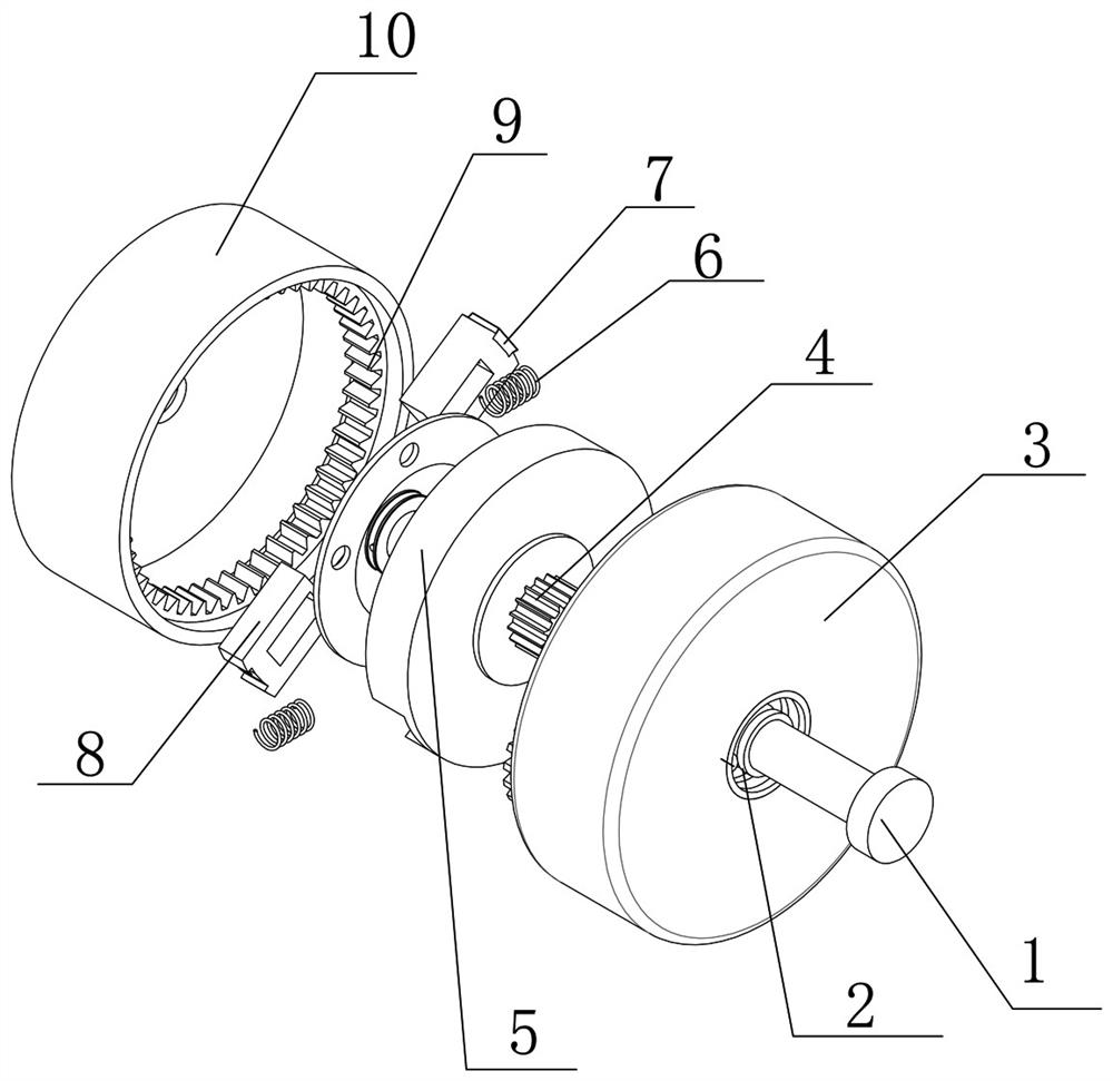
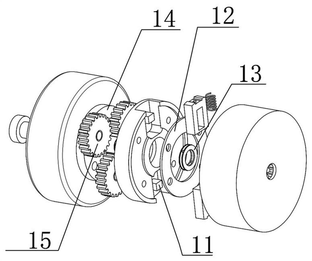
[0015] see Figure 1-2 , the present invention provides a technical solution: a speed-limiting wheel, including a traveling wheel 3, a bearing 2 is provided at the center of the traveling wheel 3, a shaft 1 runs through the bearing 2, and a speed-limiting assembly is installed at one end of the shaft 1 to limit The speed assembly includes a brake disc 5, a brake disc bearing 13 matched with the shaft 1 is provided at the center of the brake disc 5, a driven ge...


PUM


Abstract

The invention discloses a speed limiting wheel. The speed limiting wheel comprises a walking wheel, wherein a bearing is arranged at the center position of the walking wheel, a shaft penetrates through the bearing, a speed limiting assembly is installed at one end of the shaft, the speed limiting assembly comprises a brake disc, a brake disc bearing matched with the shaft is arranged at the center position of the brake disc, and a driven gear is arranged at the center position of the front face of the brake disc. In the rapid rotating process of the walking wheel, a brake block can generate centrifugal motion, the elastic potential energy of a speed limiting adjusting spring is overcome, and therefore a brake pad on the brake block and the inner wall of a speed limiting disc generate friction, the brake disc is forced to slow down, three planetary gears meshed with the driven gear are slowed down, and the purpose of speed reduction of the walking wheel is achieved after the planetary gears are slowed down.

Description

technical field [0001] The invention relates to the technical field of braking, in particular to a speed limiting wheel. Background technique [0002] Carts are often used to carry heavy objects in construction operations. The wheels in existing carts do not have the function of speed limit. Due to the high inertia of heavy objects, once the speed is too fast, it will cause safety hazards. Therefore, we designed A speed limiter. Contents of the invention [0003] The purpose of the present invention is to provide a speed limiting wheel to solve the problems raised in the background art above. [0004] In order to achieve the above object, the present invention provides the following technical solutions: a speed limiting wheel, including a traveling wheel, a bearing is provided at the center of the traveling wheel, a shaft runs through the bearing, a speed limiting assembly is installed at one end of the shaft, and the speed limiting The assembly includes a brake disc, a ...

Claims


Application Information

Patent Timeline
IPC IPC(8): F16D59/00F16D51/46F16D65/06F16D65/10F16H57/08
CPCF16D51/46F16D59/00F16D65/06F16D65/10F16H57/08
Inventor 钟钜锋
Owner 诸暨市普悦斯游乐设施工程有限公司
Why Eureka
Try Eureka