A winch clutch

A clutch and winch technology, applied in clutches, magnetic drive clutches, non-mechanical drive clutches, etc., can solve problems such as low degree of automation and affecting work efficiency

Active Publication Date: 2020-10-27
WUHAN MARINE MACHINERY PLANT
View PDF13 Cites 0 Cited by
  • Summary
  • Abstract
  • Description
  • Claims
  • Application Information

AI Technical Summary

Problems solved by technology

[0005] Since the entire control process requires the operator to manually toggle the clutch claw, the degree of automation is low, which affects work efficiency

Method used


Image

  • A winch clutch

Examples


Embodiment Construction

[0023] To make the objectives, technical solutions, and advantages of the present invention clearer, the embodiments of the present invention will be described in further detail below in conjunction with the accompanying drawings.

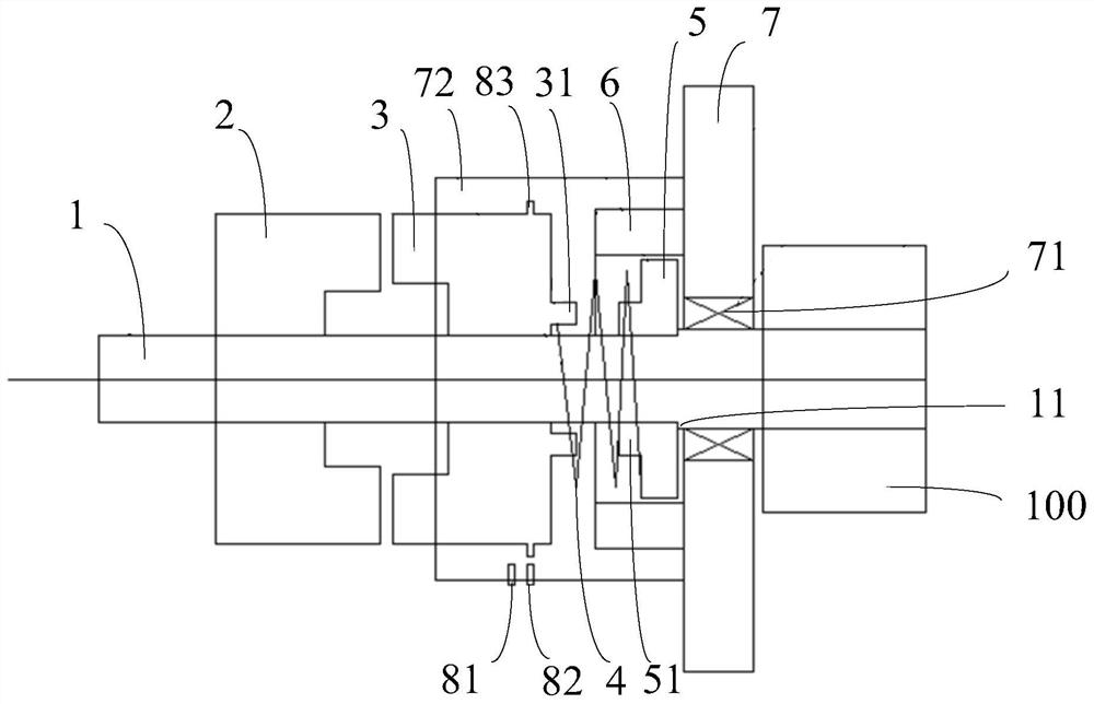
[0024] The embodiment of the present invention provides a winch clutch, such as figure 1 As shown, the winch clutch includes a main shaft 1, a main drum pawl 2 and a clutch pawl 3. The main drum pawl 2 is rotatably sleeved on the main shaft 1, and the clutch pawl 3 is axially movably sleeved on the main shaft 1. The winch clutch also includes an elastic member 4, a fixing base 5 and an electromagnet 6. The fixing base 5 and the electromagnet 6 are both sleeved on the main shaft 1. One end of the elastic member 4 is fixedly connected to the fixing base 5, and the other end of the elastic member 4 is connected to the clutch The claws 3 are fixedly connected, the elastic member 4 and the main roller claws 2 are respectively located on opposite sides of t...


PUM


Abstract

The invention discloses a winch clutch, and belongs to the field of winches. The winch clutch comprises a spindle, a main rotary drum jaw, a clutch jaw, an elastic component, a fixing seat and an electromagnet. The main rotary drum jaw rotatably sleeves the spindle, the clutch jaw axially movably sleeves the spindle, the fixing seat and the electromagnet sleeve the spindle, one end of the elasticcomponent is fixedly connected with the fixing seat, the other end of the elastic component is fixedly connected with the clutch jaw, the elastic component and the main rotary drum jaw are positionedon two opposite sides of the clutch jaw, the electromagnet is arranged towards the clutch jaw, and the clutch jaw is a ferromagnetic structural component. The winch clutch has the advantage that the work efficiency of a winch can be improved by the aid of the winch clutch.

Description

Technical field [0001] The invention belongs to the field of winches, and particularly relates to a winch clutch. Background technique [0002] A winch is a common marine machinery. A common winch usually includes a main drum and an auxiliary drum. The main drum is used to wind the steel wire rope, and the auxiliary drum is used to wind the cable. The two are driven by the same main shaft. [0003] In order to control the main drum and the auxiliary drum separately, a clutch is usually set on the winch. The clutch mainly includes a clutch claw that can rotate with the main shaft. When the main drum and the auxiliary drum need to rotate together, the operator manually toggles The clutch pawl enables the clutch pawl to engage with the main roller, and the clutch pawl drives the main roller to rotate. When the rotation of the main roller is not needed, the operator manually flips the clutch pawl in the opposite direction to make the clutch pawl and the main roller Disengage to stop t...

Claims


Application Information

Patent Timeline
Patent Type & Authority Patents(China)
IPC IPC(8): B66D1/14F16D27/10F16D27/102
CPCB66D1/14F16D27/10F16D27/102
Inventor 彭莲王鑫磊董新营周驰张文亮
Owner WUHAN MARINE MACHINERY PLANT
Why Eureka
Try Eureka