Gas detection device for underground detection

A technology of gas detection and downhole detection, which is applied in the direction of measuring devices, analyzing gas mixtures, and the structural details of gas analyzers. Longer service life, improved protection effect

Inactive Publication Date: 2021-07-02
ANHUI SAIAN ANQUAN EQUIP
View PDF0 Cites 1 Cited by
  • Summary
  • Abstract
  • Description
  • Claims
  • Application Information

AI Technical Summary

Problems solved by technology

[0004] The purpose of the present invention is to provide a gas detection device for downhole detection. By setting the installation plate and the floating plate, utilizing the cooperation of the first pulley, the second pulley, the third pulley, the traction rope and the sliding rope, the existing problems are solved. The gas detector in the well is easily soaked by stagnant water, resulting in the failure of normal detection and the decrease of service life

Method used


Image

  • Gas detection device for underground detection
  • Gas detection device for underground detection
  • Gas detection device for underground detection

Examples


Embodiment 1

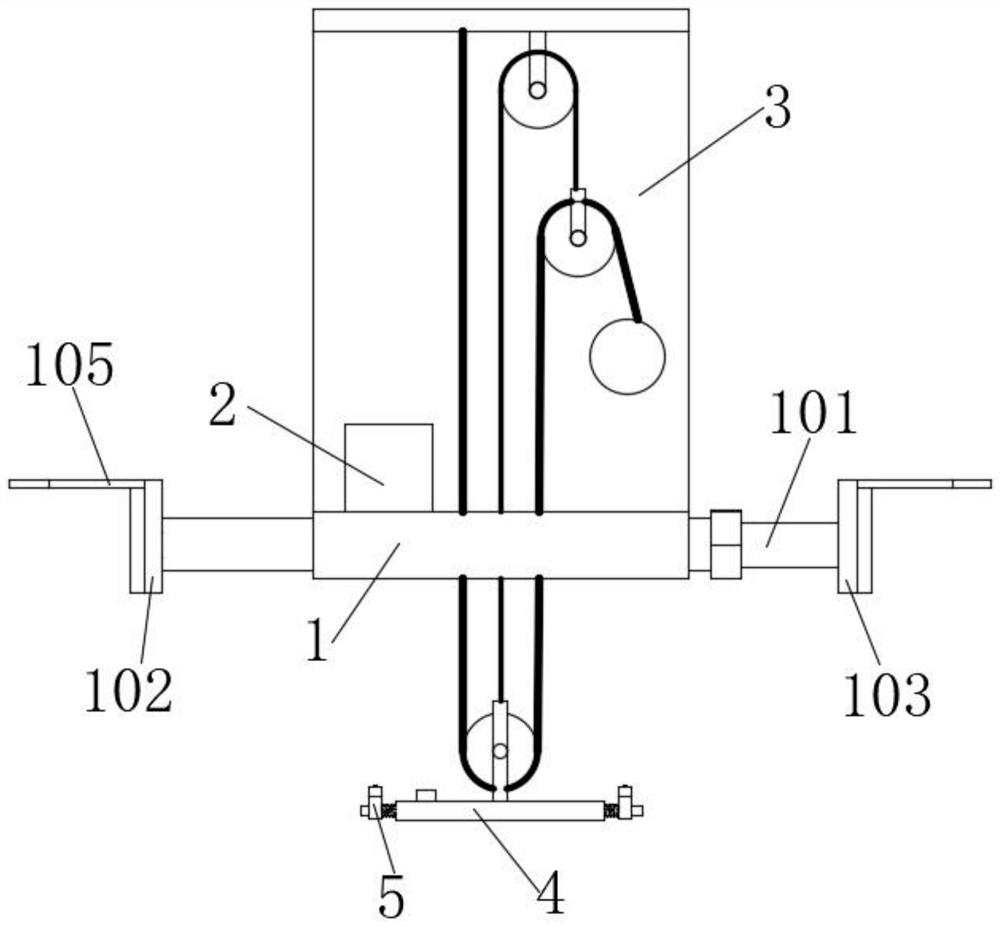
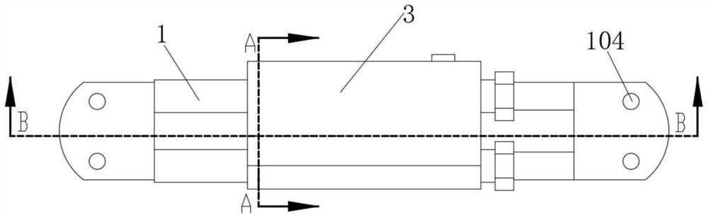
[0030] see figure 1 , figure 2 As shown, the present invention is a gas detection device for downhole detection, including a mounting plate 1, the surface of the mounting plate 1 is fixedly connected with telescopic rods 101 side by side, and the mounting plate 1 is fixed on the fixed end of the telescopic rod 101, so that the telescopic end 101 When it is close to the well wall, the mounting plate 1 will not rotate, and a sliding sleeve for fastening is provided between the telescopic end and the fixed end of the telescopic rod 101, and the gas detector 2 is fixedly connected to the upper surface of the mounting plate 1. The fixed end of the rod 101 is fixedly connected with the first fixed plate 102, and the telescopic ends of the two telescopic rods 101 are slidably connected with the second fixed plate 103; the shape and size of the first fixed plate 102 and the second fixed plate 103 are consistent, and the upper surface Both are provided with a number of fixing holes 1...

Embodiment 2

[0037] The only difference from the embodiment is that the outer wall of the L-shaped plate 3 corresponding to the reel 6 is fixedly connected with a winding motor.

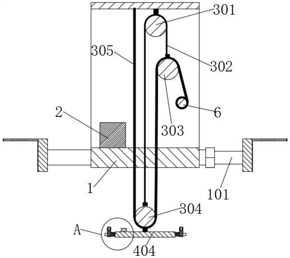
[0038]A specific application of this embodiment is: when there is accumulated water, the floating plate 4 and the probe mounting plate 5 can float on the water surface and continue to detect; when the accumulated water is too deep, the floating plate 4 and the probe mounting plate 5 float up, When reaching the position of the liquid level sensor 403, the liquid level sensor 403 sends an alarm. At this time, manually shake the handle or start the motor, utilize the reel 6 to twist the sliding rope 305, and the sliding rope 305 pulls the second pulley 303 to move downward. At this time, the traction rope 302 is pulled downwards, driving the third pulley 304 to move upwards under the traction of the sliding rope 305 and the traction rope 302, so that the floating plate 4 can shrink, reducing the erosion of the accumu...


PUM


Abstract

The invention discloses a gas detection device for underground detection, and relates to the technical field of gas detection. The device comprises a mounting plate, wherein the surface of the mounting plate is connected with a telescopic rod, and the upper surface of the mounting plate is connected with a gas detector; the bottom of an L-shaped plate is connected with a first pulley, a traction rope is wound on the first pulley, one end of the traction rope is fixedly connected with a second pulley, and the other end of the traction rope is fixedly connected with a third pulley; a sliding rope is wound around the third pulley, one end of the sliding rope is fixed to the bottom of the L-shaped plate, and the other end of the sliding rope is slidably connected with the second pulley; the lower end of the third pulley is connected with a floating plate floating on the water surface, and the surface of the floating plate is connected with sliding rods; the two ends of the two sliding rods are in sliding connection with probe mounting plates; and a gas detection probe is mounted on the upper surface of the probe mounting plate. Through cooperation of the first pulley, the second pulley, the third pulley, the traction rope and the sliding rope, the detection efficiency is improved, and the service life is prolonged.

Description

technical field [0001] The invention belongs to the technical field of gas detection, in particular to a gas detection device for downhole detection. Background technique [0002] At present, gas detectors for detecting toxic gases whose specific gravity is greater than air are usually installed on the edge of the square well or in the square well. When toxic gas leaks in the wellhead, due to its specific gravity greater than that of air, the toxic gas will accumulate at the bottom of the well. At this time, the gas detector installed on the edge of the square well cannot effectively detect the toxic gas leakage; If the gas detector is installed in the square well, there is a disadvantage of being soaked by rainwater so that it cannot work normally. [0003] In addition, after a period of use, the gas detector must be maintained to ensure the accuracy of its detection results. If the gas detector is installed in the well, it needs to be lifted out of the wellhead during ma...

Claims


Application Information

Patent Timeline
Patent Type & Authority Applications(China)
IPC IPC(8): G01N33/00
CPCG01N33/0009
Inventor 朱广朱永亮
Owner ANHUI SAIAN ANQUAN EQUIP
Why Eureka
Try Eureka