Power supply device

A power supply device and power supply technology, applied in the direction of the output power conversion device, the circuit arrangement on the support structure, the electrical components, etc., can solve the problems of increased power transmission loss and limited usable area of ​​the second plane, etc. The effect of area increase

Active Publication Date: 2021-07-02
GIGA BYTE TECH CO LTD
View PDF10 Cites 0 Cited by
  • Summary
  • Abstract
  • Description
  • Claims
  • Application Information

AI Technical Summary

Problems solved by technology

The usable area of ​​the second plane will be very limited
As a result, the transmission loss of the power supply will be increased

Method used


Image

  • Power supply device
  • Power supply device
  • Power supply device

Examples


Embodiment Construction

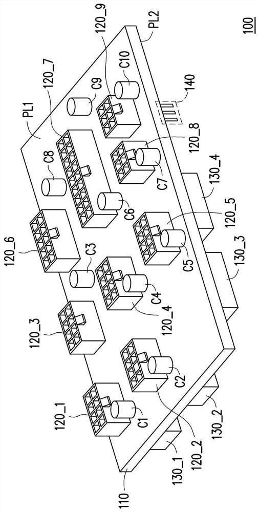
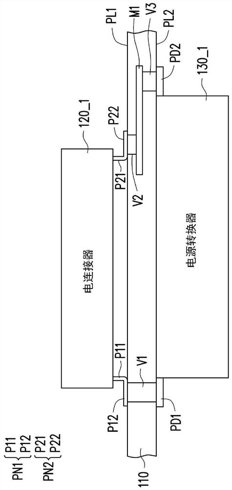
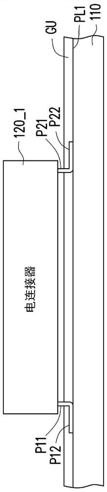
[0041] Please refer to figure 1 , figure 1 It is a schematic configuration diagram of a power supply device according to an embodiment of the present invention. In this embodiment, the power supply device 100 includes a circuit board 110 , electrical connectors 120_1 - 120_9 , and power converters 130_1 - 130_4 . The circuit board 110 has a first plane PL1 and a second plane PL2. The first plane PL1 is opposite to the second plane PL2. The electrical connectors 120_1 - 120_9 are disposed on the first plane PL1 through surface mount technology (Surface Mount Technology, SMT). The power converters 130_1 - 130_4 are disposed on the second plane PL2 by surface mount technology, respectively. The power converters 130_1 - 130_4 are respectively electrically coupled to the electrical connectors 120_1 - 120_9 via the circuit board 110 . The power converters 130_1 - 130_4 respectively provide a plurality of first power sources to at least one of the electrical connectors 120_1 - 1...


PUM


Abstract

The invention provides a power supply device. The power supply device includes a circuit board, a plurality of electrical connectors, and a plurality of power converters. The circuit board has a first plane and a second plane opposite to the first plane. The plurality of electrical connectors is arranged on the first plane by surface adhesion technology. The plurality of power converters is arranged on the second plane by surface adhesion technology. The plurality of power converters provides the plurality of first power sources to at least one of the plurality of electrical connectors via the circuit board.

Description

technical field [0001] The present invention relates to a power supply device, and in particular to a power supply device formed by surface adhesion technology. Background technique [0002] Generally, the power supply device uses a plurality of DIP (dual in-line package, dual in-line package) electrical connectors. A DIP type electrical connector is disposed on the first plane of the circuit board. However, in the case of using a DIP type electrical connector, the second plane of the circuit board opposite to the first plane will have a large number of solder joints. The usable area of ​​the second plane will be very limited. Therefore, the circuit board must be connected to the electrical connector through a connection interface such as a wire or another circuit board. In this way, the transmission loss of the power supply will be increased. Contents of the invention [0003] The invention provides a power supply device formed by surface adhesion technology. [0004...

Claims


Application Information

Patent Timeline
IPC IPC(8): H05K1/18H05K7/02H02M1/00
CPCH05K1/181H05K7/02H02M1/00H05K2201/10189
Inventor 张志隆黄文政
Owner GIGA BYTE TECH CO LTD
Why Eureka
Try Eureka