Seed knitting machine for agricultural cultivation
A seed and machine technology, applied in the field of seed weaving machines for agricultural cultivation, can solve the problems of wasting manpower, too dense plant spacing, and small seed size.
- Summary
- Abstract
- Description
- Claims
- Application Information
AI Technical Summary
Problems solved by technology
Method used
Image

Examples
Embodiment 1
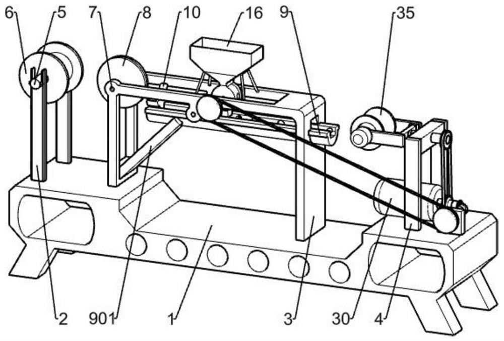
[0068] A seed weaving machine for agricultural cultivation, such as figure 1As shown, it includes a base 1, a first bracket 2, a second bracket 3, a third bracket 4, a first shaping component, a second shaping component, a blanking component, a weaving component and a power component, and the base 1 is generally long and rectangular. , including a bottom plate and four legs, the first bracket 2 includes two vertical rods, the first bracket 2 is fixed on the left end of the base 1, the second bracket 3 is an inverted U-shaped frame, and the second bracket 3 is fixed on the The upper middle part of the base 1, the third bracket 4 is an inverted U-shaped frame, the third bracket 4 is fixed on the other end of the base 1, the first shaping component and the second shaping component are fixed on the second bracket 3, the lower The material component is fixed on the second support 3 , the weaving component is set on the second support 3 and the third support 4 , and the power compon...
Embodiment 2
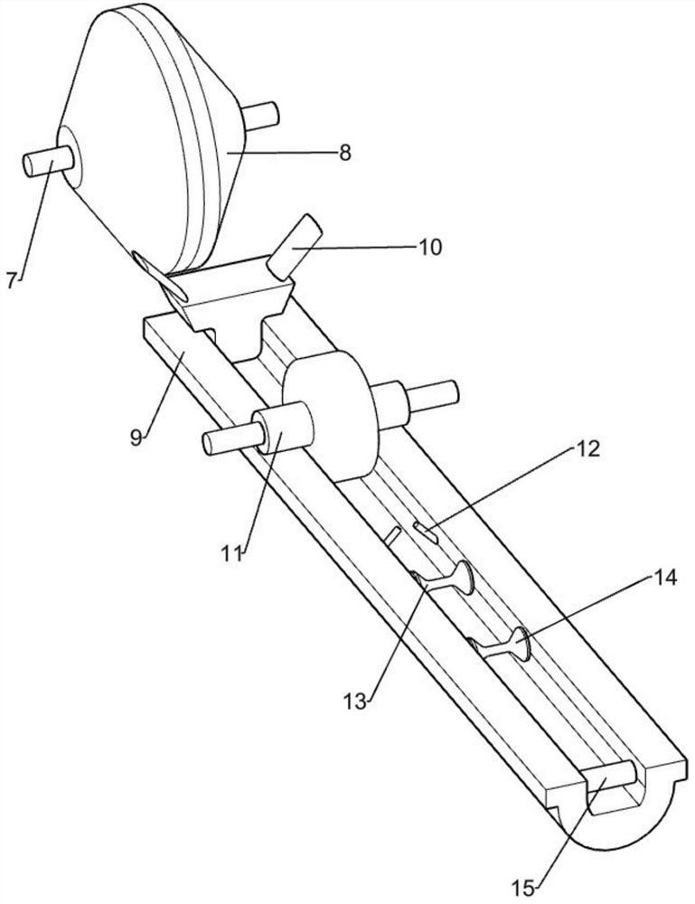
[0071] On the basis of Example 1, such as figure 2 As shown, the first sizing assembly includes a first shaft 5, a first tape roll 6, a second shaft 7, a first sizing block 8, an inclined bracket 901, a track 9, a second sizing block 10 and a third sizing block Block 11, the first rotating shaft 5 rides on the groove of the first bracket 2, the first paper tape roll 6 is fixedly arranged on the first rotating shaft 5, and the first paper tape roll 6 is wound with flat soluble wrapping paper, the second The rotating shaft 7 is rotatably installed at the upper left corner of the second bracket 3, the first shaping block 8 is fixedly arranged on the second rotating shaft 7, the left end of the inclined bracket 901 is lower, and is fixedly arranged at the lower part of the left side of the second bracket 3, The right end of oblique support 901 is higher, is fixedly connected with track 9 left ends, and track 9 right ends are fixedly installed on the second support 3, and the two ...
Embodiment 3
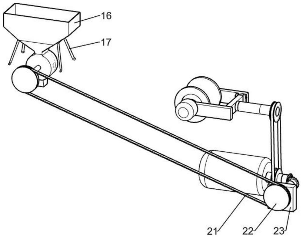
[0074] On the basis of Example 2, such as Figure 3-4 As shown, the blanking assembly includes a hopper 16, a fourth support 17, a third rotating shaft 18, a first rotating wheel 19, a rotating disk 20, a first belt 21, a second rotating wheel 22, a support plate 23 and a fourth rotating shaft 24, The upper part of the hopper 16 is a bucket shape with a wide top and a narrow bottom. The lower part of the hopper 16 is a cylindrical cavity. The lowermost end of the hopper 16 is a square opening. The fourth support 17 is four inclined columns. On the second bracket 3, the upper end of the fourth bracket 17 is fixedly connected with the hopper 16, the third rotating shaft 18 is rotatably installed on the second bracket 3, and the turntable 20 is fixed on the third rotating shaft 18, and the turntable 20 is located at the lower part of the hopper 16 In the cylindrical chamber, there are several grooves evenly divided on the turntable 20, the grooves on the turntable 20 can accommod...
PUM
 Abstract
Description
Claims
Application Information
 - R&D
- Intellectual Property
- Life Sciences
- Materials
- Tech Scout
- Unparalleled Data Quality
- Higher Quality Content
- 60% Fewer Hallucinations
Browse by: Latest US Patents, China's latest patents, Technical Efficacy Thesaurus, Application Domain, Technology Topic, Popular Technical Reports.
© 2025 PatSnap. All rights reserved.Legal|Privacy policy|Modern Slavery Act Transparency Statement|Sitemap|About US| Contact US: help@patsnap.com