
Big data-based detector for cardiovascular medicine department

A detector and cardiovascular technology, which is applied in the field of cardiovascular internal medicine detector based on big data, can solve the problems of instrument damage, falling, and affecting the normal use of the instrument.

Pending Publication Date: 2021-07-06
刘宝
View PDF0 Cites 0 Cited by
  • Summary
  • Abstract
  • Description
  • Claims
  • Application Information

AI Technical Summary

Problems solved by technology

[0004] With the development of science and technology, cardiovascular detectors have become smaller and more portable, but the existing cardiovascular detectors cannot achieve the purpose of fixing, and often fall due to collisions, causing damage to the instrument and affecting the instrument. normal use

Method used


Image

  • Big data-based detector for cardiovascular medicine department
  • Big data-based detector for cardiovascular medicine department
  • Big data-based detector for cardiovascular medicine department

Examples


Embodiment 1

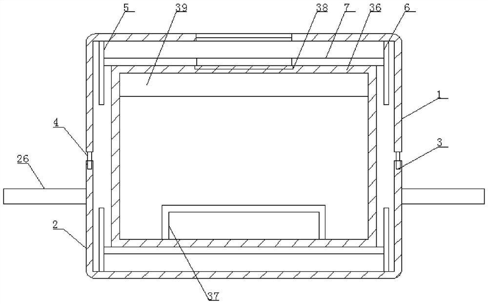
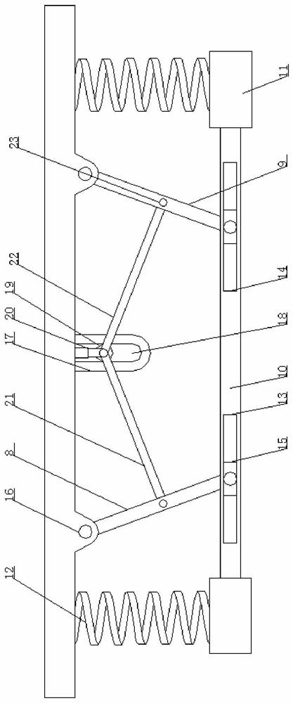
[0034] Such as Figure 1-7 As shown, the cardiovascular medicine detector according to the embodiment of the present invention includes a housing one 1 and a housing two 2 located at the top of the housing one 1, the top of the housing one 1 is provided with a fixing groove 3, so The bottom end of the housing two 2 is provided with an insert 4 that matches the fixing groove 3, and the ends of the housing one 1 and the housing two 2 that are close to each other are provided with a symmetrically arranged limiting plate one. 5 and two limiting plates 6, between the limiting plate one 5 and the two limiting plates 6, there are horizontally arranged horizontal plates 7, and the horizontal plates 7 are respectively connected with the housing one by a buffer mechanism. 1 is connected to the housing two 2;

[0035] Wherein, the buffer mechanism includes inclined rod one 8 and inclined rod two 9 which are symmetrically arranged on the horizontal plate 7, and the bottom ends of the fir...

Embodiment 2

[0039] Such as Figure 1-7 As shown, one side of the stroke groove 34 is provided with a damping spring 35 arranged horizontally, and rubber pads are provided on the sides of the vertical rods 33 away from each other, and the first chute 13 and the second chute 14 are connected to each other. The far side is provided with a buffer spring corresponding to the sliding block 15 .

Embodiment 3

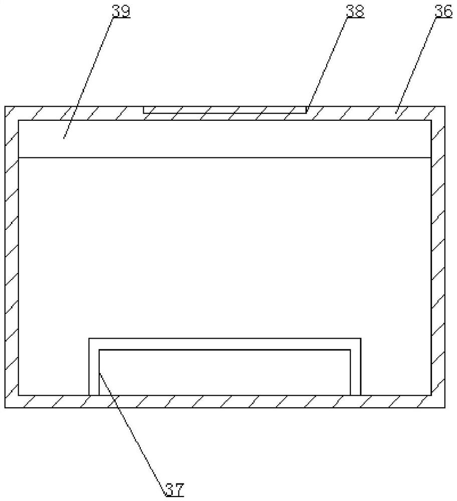
[0041] Such as Figure 1-7 As shown, a tester casing 36 is provided between the two groups of said horizontal plates 7, and a pulse sensor 37 matching it is arranged in the said tester casing 36, and a display is arranged on the top of said tester casing 36. screen 38, the top of the horizontal plate 7 and the housing two 2 are provided with holes matching the display screen 38, the detector casing 36 is provided with a storage battery 39, and the detector casing One side of the battery 36 is provided with a charging interface electrically connected to the storage battery 39 .


PUM


Abstract

The invention discloses a big data-based detector for the cardiovascular medicine department. The detector comprises a shell I and a shell II located at the top end of the shell I; fixing grooves are formed in the top end of the shell I; the bottom end of the shell II is provided with insertion blocks matched with the fixing grooves; a limiting plate I and a limiting plate II symmetrically arranged are arranged at the ends, close to each other, of the shell I and the shell II correspondingly; a transverse plate transversely arranged is arranged between the limiting plate I and the limiting plate II and connected with the shell I and the shell II through buffering mechanisms. The detector has the beneficial effects that a good fixing effect is achieved, thus avoiding that an instrument is damaged by the fact that the instrument falls due to collision, so that normal use of the instrument is guaranteed, and meanwhile the heartbeat rate is conveniently measured; when the detector needs to be fixed on a wrist, a bandage is fixed on an arm through a clamping mechanism, while protrusion blocks are engaged with grooves, so that the bandage is fixed; and the detector is simple in structure, convenient to operate and suitable for being popularized and used.

Description

technical field [0001] The invention relates to the technical field of medical devices, in particular to a large data-based cardiovascular internal medicine detector. Background technique [0002] Medical equipment is the most basic element of medical treatment, scientific research, teaching, institutions, and clinical disciplines, including professional medical equipment and household medical equipment. Medical equipment is the basic condition for continuously improving the level of medical science and technology, and it is also an important symbol of modernization. Medical equipment has become an important field of modern medicine. The development of medical treatment depends to a large extent on the development of instruments, and even in the development of the medical industry, its breakthrough of bottlenecks also plays a decisive role. [0003] Cardiovascular detector, also called "cardiovascular diagnostic instrument", is a medical device that reflects heart function,...

Claims


Application Information

Patent Timeline
Patent Type & Authority Applications(China)
IPC IPC(8): A61B5/024
CPCA61B5/024A61B5/02438A61B5/02444
Inventor 不公告发明人
Owner 刘宝
Learn More