Two-end press-fit equipment for nut special for automobile fastener

A technology of pressing equipment and fasteners, which is applied in the field of auto parts processing and can solve problems such as slow work efficiency

Pending Publication Date: 2021-07-06
上海东风汽车专用件有限公司
View PDF0 Cites 0 Cited by
  • Summary
  • Abstract
  • Description
  • Claims
  • Application Information

AI Technical Summary

Problems solved by technology

[0004] The object of the present invention is to provide a kind of two-end pressing equipment for special nuts of

Method used


Image

  • Two-end press-fit equipment for nut special for automobile fastener
  • Two-end press-fit equipment for nut special for automobile fastener
  • Two-end press-fit equipment for nut special for automobile fastener

Examples


Embodiment 1

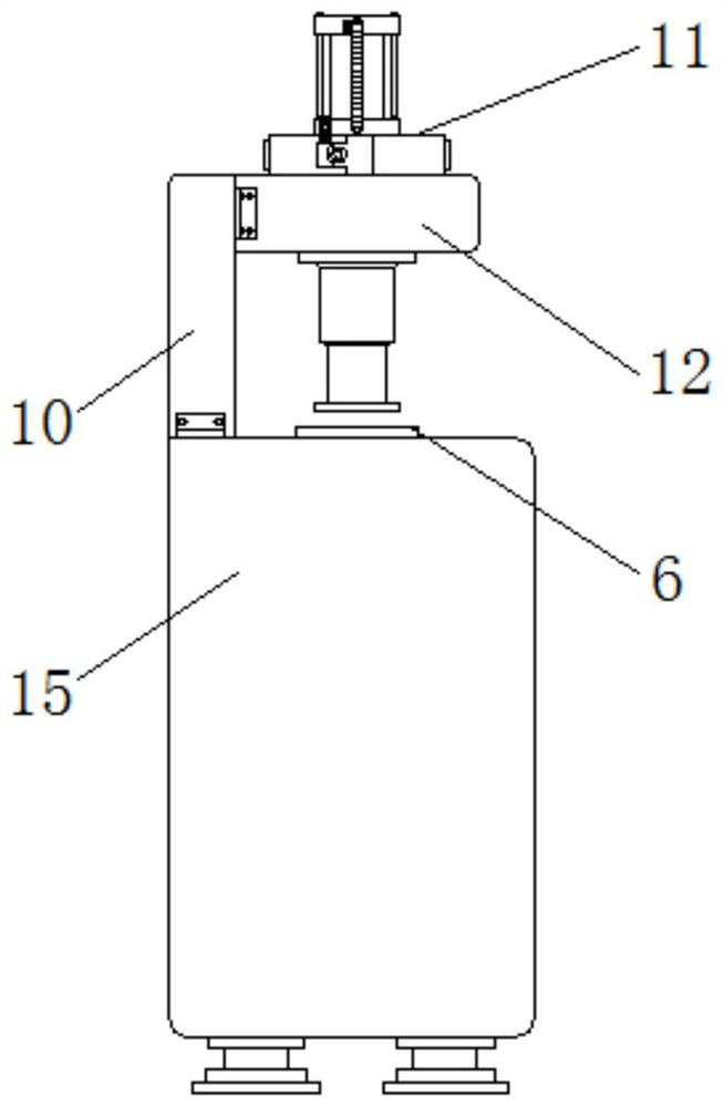
[0026] Example 1: See Figure 1-5 , a two-end pressing device for special nuts for automobile fasteners, including a main box 15, a moving structure 8 for accelerating work efficiency, a positioning structure 9 for precise processing, and a clamping structure for easy operation;

[0027] The top of the main box 15 is provided with a chute 17, and the inside of the chute 17 is slidably connected with two placement plates 6, one end of the top of the chute 17 is equipped with a vertical plate 10, and the top of one end of the vertical plate 10 is equipped with a top plate 12, A cylinder 11 is installed at the top center of the top plate 12, the model of the cylinder 11 can be SC63, and the bottom of the cylinder 11 penetrates to the bottom of the top plate 12, and the moving structure 8 is arranged inside the main box 15 below the chute 17;

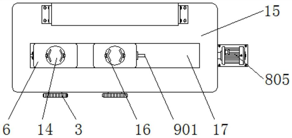
[0028] Empty slots 14 are provided at the middle position of the top of the placement plate 6, and the positioning structure 9 is arranged...

Embodiment 2

[0034] Embodiment 2: The moving structure 8 includes a connecting plate 801, a second sleeve 802, a cavity 803, a second screw mandrel 804 and a servo motor 805. The cavity 803 is set inside the main box 15 below the chute 17, and the servo motor 805 is installed on the top of one side of the main box 15, the model of the servo motor 805 can be RDX-201-V36F5E13, the output end of the servo motor 805 is connected with a second screw mandrel 804, and the second screw mandrel 804 inside the cavity 803 The outer wall is slidingly connected with two second sleeves 802, and the tops of the second sleeves 802 are connected with connecting plates 801, and the tops of the connecting plates 801 are connected with the placement plate 6;

[0035] One end of the second screw rod 804 runs through the inside of the cavity 803, and one end of the second screw rod 804 is connected to the inner wall of the cavity 803 through a rotating shaft;

[0036] Specifically, as figure 1 and image 3 As...

Embodiment 3

[0037] Embodiment 3: The positioning structure 9 includes a guide rod 901, an electric shock groove 902, a first magnet 903, a contact 904 and a second magnet 905. The guide rods 901 are all arranged on the side where the placement plate 6 is far away from each other, and the electric shock grooves 902 are Open inside the main box 15 on both sides of the chute 17, a first magnet 903 is provided on one side of the electric shock groove 902, and a second magnet 905 is slidably connected to the electric shock groove 902 on the first magnet 903 side, and the second A contact 904 is installed on the side of the magnet 905 close to the first magnet 903;

[0038] Specifically, as figure 1 , image 3 and Figure 5 As shown, when using this mechanism, while the placement plate 6 moves, the guide rod 901 moves, and the guide rod 901 is inserted into the electric contact slot 902, pushing the second magnet 905 and the contact 904 to slide toward the first magnet 903 at the same time unti...


PUM


Abstract

The invention discloses two-end press-fit equipment for a nut special for an automobile fastener, and relates to the technical field of automobile part machining. The two-end press-fit equipment comprises a main box, and further comprises a moving structure for improving the working efficiency, a positioning structure for precise machining and a clamping structure convenient to operate, and a sliding groove is formed at the top end of the main box; and two placing plates are slidably connected into the sliding groove, a vertical plate is installed at one end of the top end of the sliding groove, a top plate is installed at the top end of one end of the vertical plate, an air cylinder is installed at the center of the top end of the top plate, and the bottom end of the air cylinder penetrates to the position below the top plate. A rotating rod is rotated, a driving gear rotates, a driven gear is driven to rotate, so that a first lead screw rotates, under cooperation of threads of a first sleeve, the first sleeve can move, and therefore clamping plates are driven to move until the two clamping plates fix a part, and the structure is beneficial for improving the convenience of the device.

Description

technical field [0001] The invention relates to the technical field of automobile parts processing, in particular to a two-end pressing device for special nuts of automobile fasteners. Background technique [0002] There are both nylon gaskets and metal gaskets in the special nuts for automobile fasteners. The normal process in the industry is to press the nylon gasket or the metal gasket first. This kind of process has many procedures and high cost. This equipment can be pressed at the same time. Nylon washers and metal pads improve work efficiency. Now a kind of fast processing efficiency and convenient use of two-end pressing equipment for nuts is needed, and the existing two-end pressing equipment for automobile fasteners special nuts also has Much to be desired. [0003] The traditional two-end pressing equipment for special nuts for automotive fasteners has a slow working efficiency and can only process a single part. The operation process is time-consuming, laborious...

Claims


Application Information

Patent Timeline
IPC IPC(8): B23P19/02B23Q3/06
CPCB23P19/02B23Q3/06
Inventor 汤斌杰熊亚萍周伟民杜彦佼
Owner 上海东风汽车专用件有限公司
Why Eureka
Try Eureka