A cylinder jet printing device and system
A cylinder and tooling technology, applied to printing devices, printing, typewriters, etc., can solve problems such as poor consistency, high cost, and manual missing printing, and achieve the effects of flexible applicability, convenient operation, and simple structure
- Summary
- Abstract
- Description
- Claims
- Application Information
AI Technical Summary
Problems solved by technology
Method used
Image
Examples
Embodiment 1
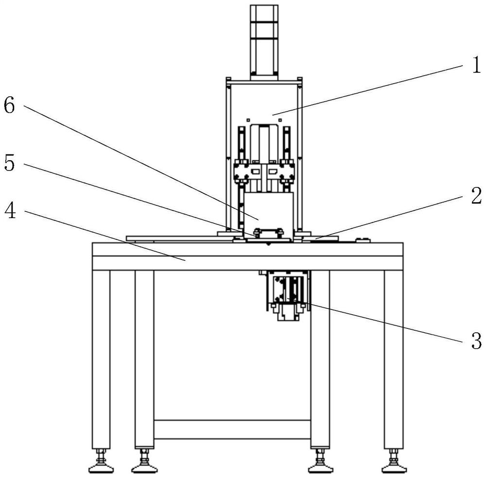
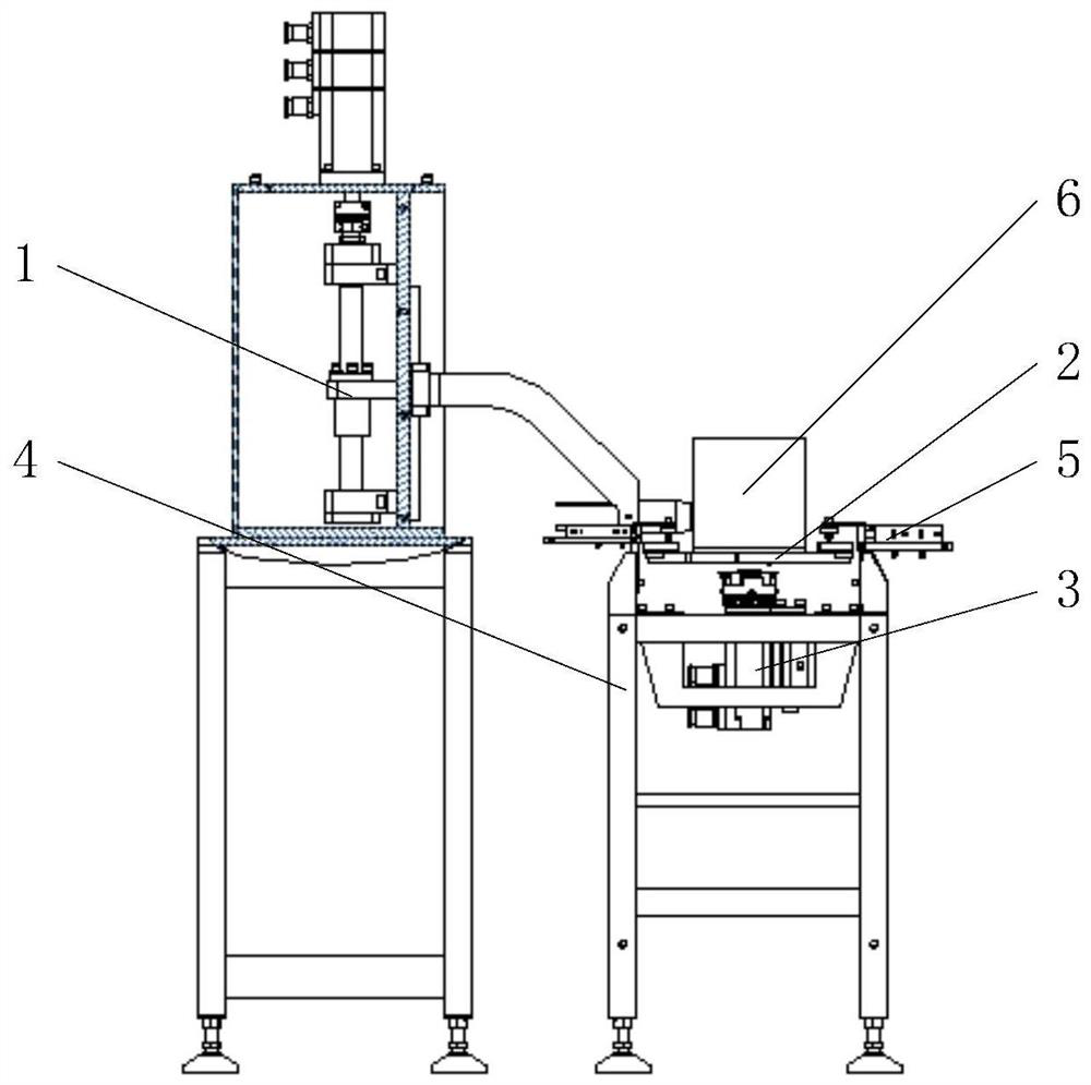
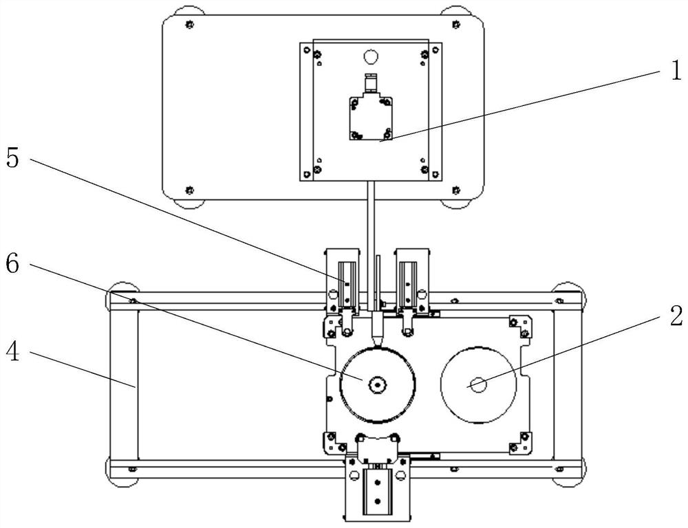
[0036] This embodiment provides a cylinder body jet printing device, including a jacking and rotating mechanism 3, and the jacking and rotating mechanism 3 is mainly used for adsorbing and fixing the lightweight cylinder 6, moving the lightweight cylinder 6 up and down, and rotating the lightweight cylinder 6, so as to realize Adjusting the position of the lightweight cylinder 6 is convenient for the printing mark 104 of the inkjet printer 1 to perform the printing operation on the outer wall of the lightweight cylinder 6 . The jacking-up rotating mechanism 3 includes a mounting bracket 301 , a rotating drive member, a jacking-up drive member, a mounting plate 304 and a support base 307 ;
[0037] The mounting bracket 301 is detachably mounted on the transmission line body 4 through bolts, and is located below the transmission line body 4 .
[0038] The fixed end of the jacking driver can be installed on the mounting bracket 301 by detachable connection methods such as bolts, ...
Embodiment 2
[0043] Further improvements are made on the basis of Embodiment 1. The jacking drive member and the rotation drive member can be realized by using two sets of components, or a mechanism with both jacking and rotating functions can be used. The lifting driving member and the rotating driving member designed in this embodiment have the advantages of simple setting structure, flexible operation and low cost, and can effectively carry the lightweight cylinder 6 to achieve rapid lifting and rotating actions, specifically:
[0044] 1. The jacking drive part adopts the jacking cylinder 303. The cylinder body of the jacking cylinder 303 is mounted on the mounting bracket 301 through detachable connecting parts such as bolts, and the mounting plate 304 is mounted on the piston end of the jacking cylinder 303.
[0045] 2. The rotary drive includes a rotary motor 302, a driving gear 305 and a driven gear 306 mounted on the mounting plate 304; the output shaft of the rotary motor 302 and t...
Embodiment 3
[0048] On the basis of Embodiment 2, it is further improved, and also includes an inkjet printer 1. The inkjet printer 1 includes a frame 101, a lifting mechanism and a printing mark 104. The lifting mechanism is installed on the frame 101. The lifting mechanism is used to drive The jet-printing mark 104 moves up and down, and the jetting end of the jet-printing mark 104 is used to jet-print the outer wall of the lightweight cylinder 6 .
[0049] Specifically, the design of the lifting mechanism is as follows: the lifting mechanism includes a driving screw 103, a linear slide rail 106, a motor 110 and a marking mounting plate 105; a mounting vertical plate 107 is provided on the top surface of the rack 101, and the shaft of the driving screw 103 It is rotatably connected to the bearing seat 108 at both ends, and the bearing seat 108 and the linear slide rail 106 at both ends are fixed on the installation vertical plate 107 of the frame 101; the sliding direction of the linear s...
PUM
 Abstract
Description
Claims
Application Information
 - R&D
- Intellectual Property
- Life Sciences
- Materials
- Tech Scout
- Unparalleled Data Quality
- Higher Quality Content
- 60% Fewer Hallucinations
Browse by: Latest US Patents, China's latest patents, Technical Efficacy Thesaurus, Application Domain, Technology Topic, Popular Technical Reports.
© 2025 PatSnap. All rights reserved.Legal|Privacy policy|Modern Slavery Act Transparency Statement|Sitemap|About US| Contact US: help@patsnap.com


