Chain type feeding and conveying device of net rack pipe end circular seam full-automatic welding machine

A conveying device and chain conveying technology, which is applied in the field of fully automatic welding machines for grid pipe end ring seams, can solve problems such as waste of human resources, and achieve the effects of reducing labor intensity, good stability and safety, and simple and reasonable structure

Pending Publication Date: 2021-07-06
田国华
View PDF2 Cites 2 Cited by
  • Summary
  • Abstract
  • Description
  • Claims
  • Application Information

AI Technical Summary

Problems solved by technology

[0002] At present, the automatic welding of the ring seam at the end of the grid pipe requires manual spot welding of the pipe to be welded and the sealing plate before welding, and then puts the pipe to be welded on the welding workbench for automatic welding, so manual work is required during the welding process. The loading operation of welded pipes is a serious waste of human resources

Method used


Image

  • Chain type feeding and conveying device of net rack pipe end circular seam full-automatic welding machine
  • Chain type feeding and conveying device of net rack pipe end circular seam full-automatic welding machine
  • Chain type feeding and conveying device of net rack pipe end circular seam full-automatic welding machine

Examples


Embodiment Construction

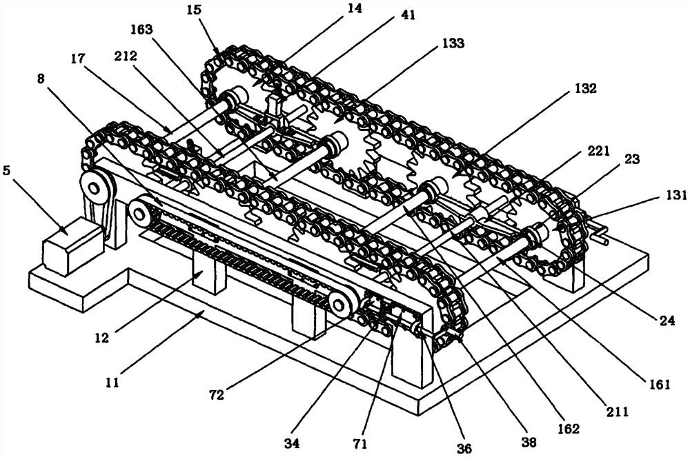
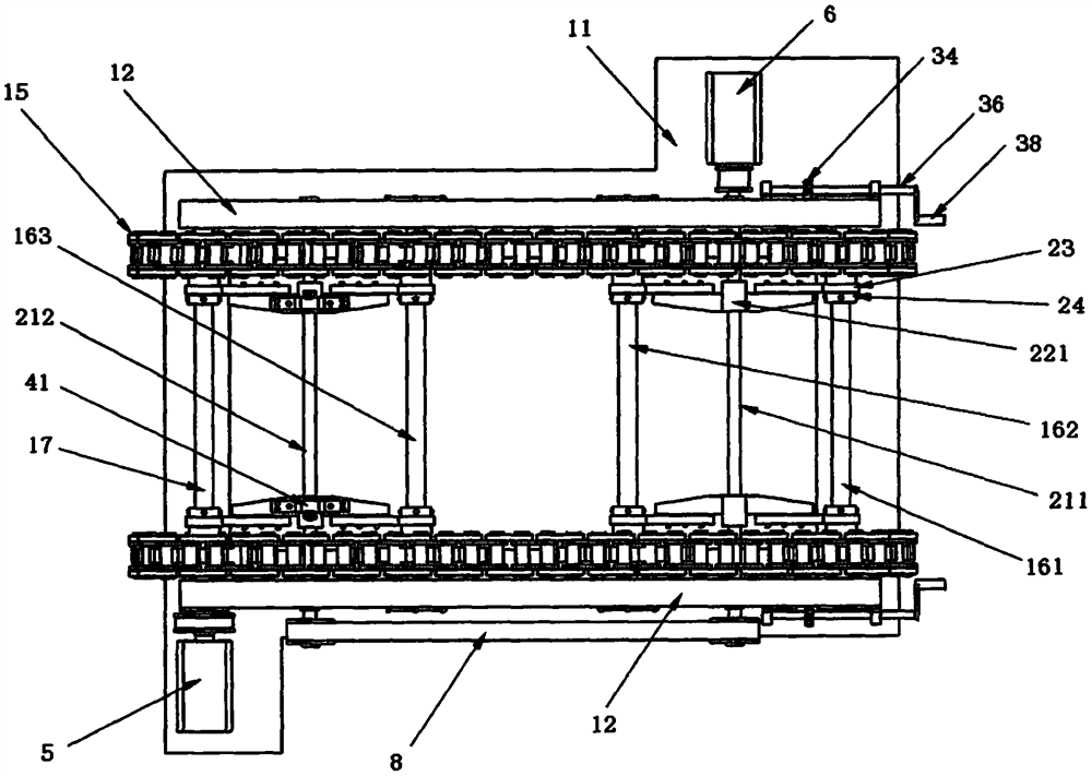
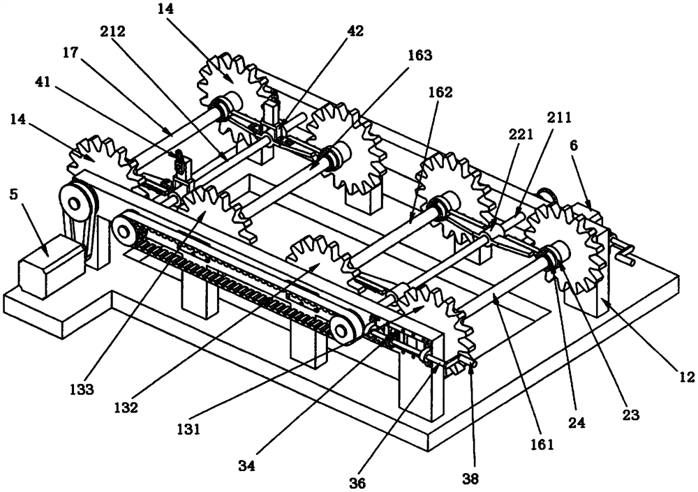
[0039] Such as Figure 1-19 As shown, this specific embodiment adopts the following technical solutions: a chain-type feeding and conveying device for a fully automatic welder for the pipe end ring seam of a network frame, including a chain conveying mechanism 1, a position adjusting mechanism 2, a tension adjusting mechanism 3, a waiting Welded pipe position detection device 4, the input end of the chain conveying mechanism 1 is manually loaded, the output end of the chain conveying mechanism 1 is equipped with a fully automatic welding machine, and the chain conveying mechanism 1 includes a machine base 11 and a frame 12 , driven sprocket 13, driving sprocket 14, transmission chain 15, slide shaft 16, rotating shaft 17, described frame 12 is provided with two, offers chute on the described frame 12, slides in the chute A sliding shaft 16 is installed, and a cylindrical hole is provided on the frame 12, and a rotating shaft 17 and a screw mandrel 21 are respectively rotated i...


PUM


Abstract

The invention discloses a chain type feeding and conveying device of a net rack pipe end circular seam full-automatic welding machine. The chain type feeding and conveying device of the net rack pipe end circular seam full-automatic welding machine comprises a chain conveying mechanism, a position adjusting mechanism, a tension adjusting mechanism and a to-be-welded pipe position detecting device, wherein the input end of the chain conveying mechanism is used for manual feeding, and the full-automatic welding machine is mounted at the output end of the chain conveying mechanism; the chain conveying mechanism comprises a machine base, machine frames, driven chain wheels, driving chain wheels, conveying chains, sliding shafts and rotating shafts, wherein the number of the machine frames is two, the sliding shafts are mounted in sliding grooves formed in the machine frames in a sliding mode, the rotating shafts and lead screws are rotationally mounted in cylindrical holes formed in the machine frames correspondingly, the two driven chain wheels are rotationally mounted on the two sides of each sliding shaft; the two sides of each rotating shaft are connected and provided with two driving chain wheels through sliding flat keys, the driven chain wheels and the driving chain wheels are provided with the conveying chains in a meshed mode, the number of the conveying chains is two, one end of each rotating shaft is in transmission connection with a motor through belt transmission. The chain type feeding and conveying device of the net rack pipe end circular seam full-automatic welding machine is simple and reasonable in structure and convenient to use; after a plurality of to-be-welded pipes are placed on the chain type feeding and conveying device at a time, full-automatic conveying of the whole welding process of the to-be-welded pipes can be achieved under driving of the motor, the conveying process is safe and reliable, the labor intensity of conveying is reduced, and the conveying efficiency is improved.

Description

technical field [0001] The invention relates to a fully automatic welding machine for the circular seam at the pipe end of a network frame, in particular to a chain-type feeding and conveying device. Background technique [0002] At present, the automatic welding of the ring seam at the end of the grid pipe requires manual spot welding of the pipe to be welded and the sealing plate before welding, and then puts the pipe to be welded on the welding workbench for automatic welding, so manual work is required during the welding process. The feeding operation of welded pipes is a serious waste of human resources. The main problems faced in the design of the fully automatic special welding machine for the pipe end ring seam of the grid frame are as follows: one is the design of the automatic up and down welding workbench device for the pipe to be welded, the other is the automatic detection of the length of the pipe to be welded, and the third is the feeding of the pipe to be wel...

Claims


Application Information

Patent Timeline
IPC IPC(8): B65G17/38B65G23/06
CPCB65G17/38B65G23/06
Inventor 田国华田瑜昕汪蕾
Owner 田国华
Why Eureka
Try Eureka