
Zero-discharge treatment device for medical blood sewage

A treatment device and zero discharge technology, which is applied in the direction of heating water/sewage treatment, oxidized water/sewage treatment, multi-stage water/sewage treatment, etc., can solve the treatment requirements that cannot meet zero discharge, and cannot meet the advanced treatment of pathogenic microorganisms And other issues

Inactive Publication Date: 2021-07-06
刘晓燕
View PDF0 Cites 0 Cited by
  • Summary
  • Abstract
  • Description
  • Claims
  • Application Information

AI Technical Summary

Problems solved by technology

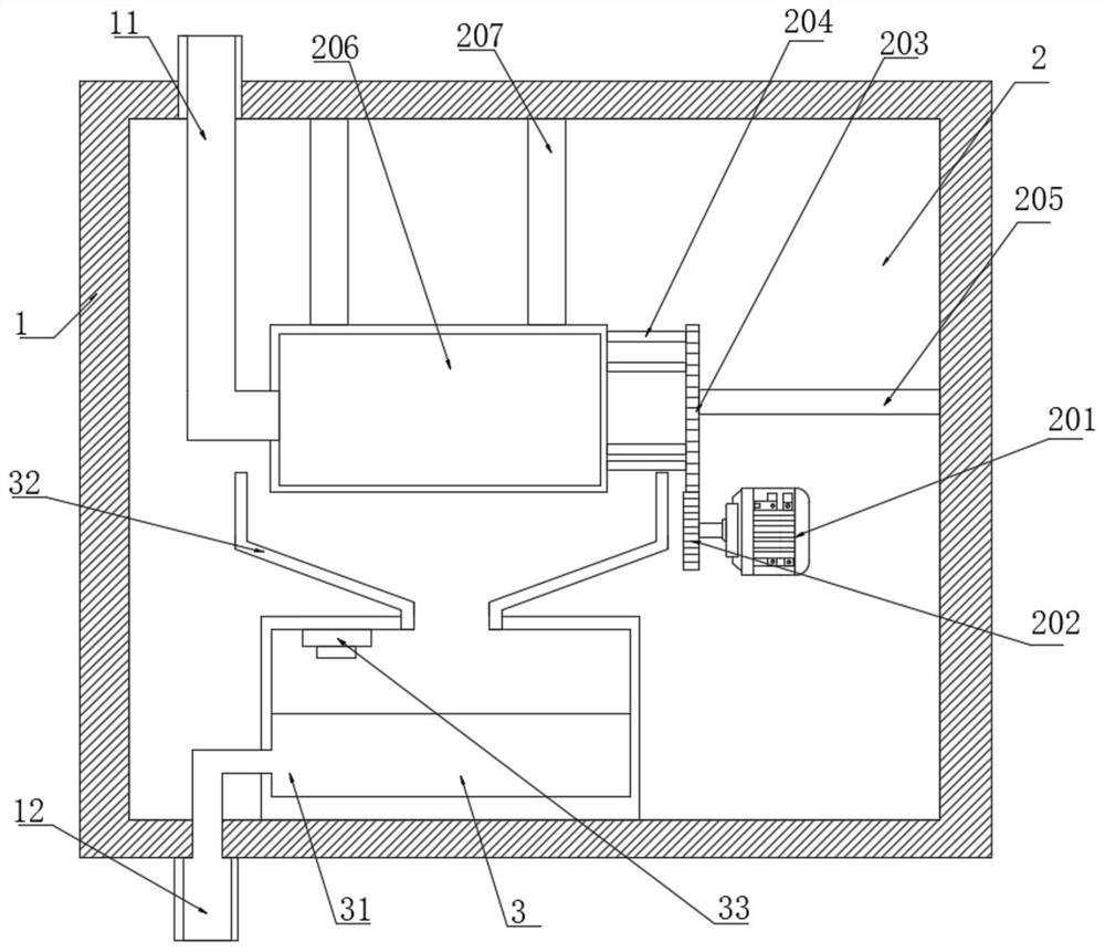
[0005] The purpose of the present invention is to provide a zero-discharge treatment device for medical blood sewage to solve the problem that the above-mentioned existing zero-discharge treatment device for sewage cannot achieve advanced treatment of pathogenic microorganisms and cannot meet the treatment requirements of zero discharge.

Method used


Image

  • Zero-discharge treatment device for medical blood sewage
  • Zero-discharge treatment device for medical blood sewage
  • Zero-discharge treatment device for medical blood sewage

Examples


Embodiment 1

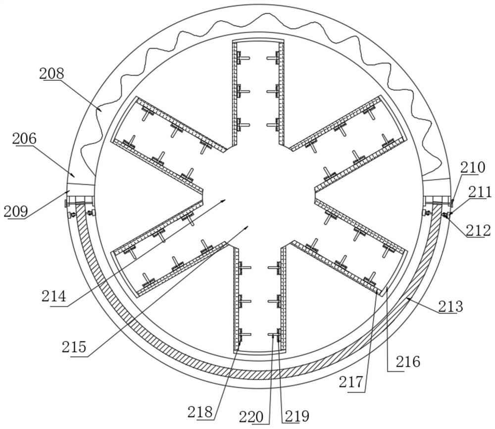
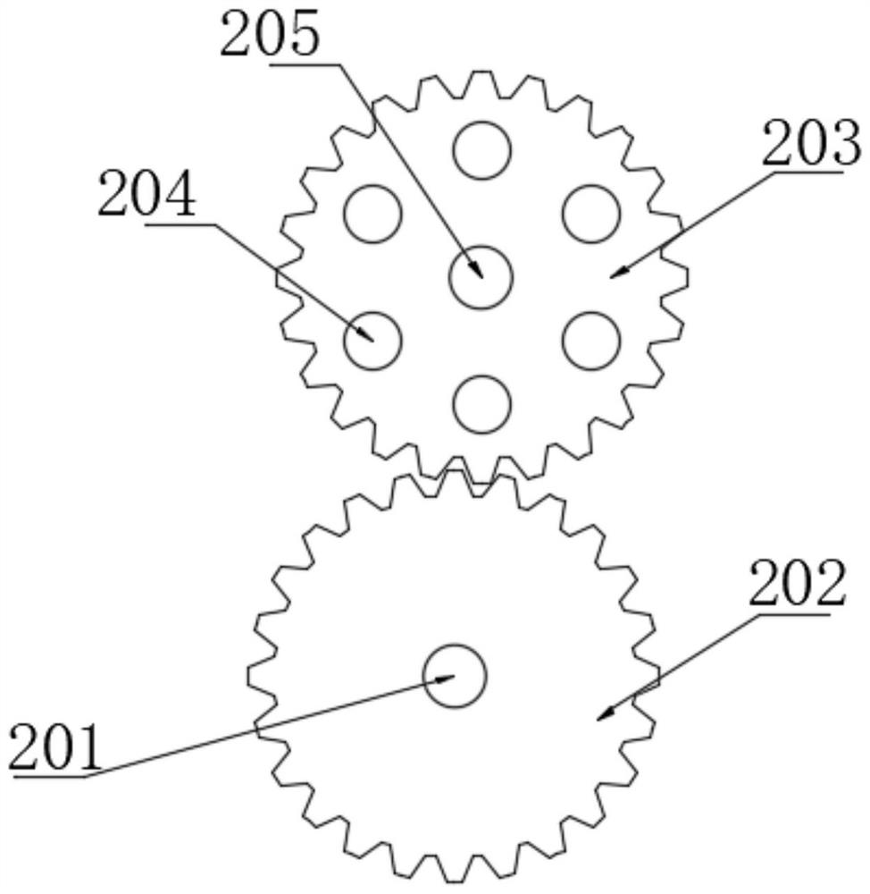
[0026] Such as Figure 1-5 As shown, a medical bloody sewage zero-discharge treatment device includes a housing 1, a water inlet pipe 11 is fixedly installed on the top surface of the housing 1, an outlet pipe 12 is fixedly installed on the bottom surface of the housing 1, and the inner cavity of the housing 1 is fixed A first-level processing mechanism 2 is installed, and the first-level processing mechanism 2 includes a motor 201. The output shaft of the motor 201 is fixedly sleeved with a first transmission gear 202, and the tooth surface of the first transmission gear 202 is meshed with a second transmission gear 203. The surface of the transmission gear 203 is fixedly installed with a connecting rod 204, and the shaft center of the second transmission gear 203 is fixedly sleeved with a mounting rod 205, and the end of the connecting rod 204 away from the second transmission gear 203 is fixedly connected with a primary treatment chamber 206. A fixed rod 207 is fixedly inst...

Embodiment 2

[0036] Such as Figure 6 As shown, the difference between the present embodiment and Embodiment 1 is: the side of the secondary treatment chamber 31 is fixedly equipped with an ozone generator 34, and the top surface of the ozone generator 34 is fixedly connected with an air inlet pipe 35, and the air inlet pipe 35 is away from the ozone One end of generator 34 is fixedly connected with shower head 36, and shower head 36 is fixedly installed on the inner cavity top surface of secondary treatment chamber 31, produces ozone through air inlet pipe 35, shower head 36 to the inner cavity of secondary treatment room 31 by ozone generator 34 The sewage is sterilized at a deep level, so as to completely remove the source of pathogens and prevent infectious bacteria from lurking in the sewage.


PUM


Abstract

The invention belongs to the field of sewage discharge treatment, and particularly relates to a zero-discharge treatment device for medical blood sewage. The device comprises a shell, a primary treatment mechanism and a secondary treatment mechanism, and the primary treatment mechanism comprises a motor, a first transmission gear, a second transmission gear, a connecting rod, a mounting rod, a primary treatment chamber, a fixed rod, a heating wire, a clamping block, a pin rod, a base, a roller, a primary filter membrane, a connector, a connecting pipe, a branch pipe and the like. The first transmission gear is driven by a motor to rotate so as to enable a primary treatment chamber to rotate, sewage in a connecting pipe enters a plurality of branch pipes due to the action of centripetal force, two springs are fixedly connected with a swing plate, so that the swing plate can delay the time of water flow rushing out of the branch pipes, and the water flow is more completely filtered by a secondary filtering membrane; and the primary filter membrane is fixedly mounted at the lower end of the inner wall of the secondary treatment chamber, and the top end of the roller is tangent to the side surface of the primary filter membrane, so that the mounting resistance of the primary filter membrane is conveniently reduced.

Description

technical field [0001] The invention belongs to the field of sewage discharge treatment, in particular to a zero-discharge treatment device for medical blood sewage. Background technique [0002] During the daily work of the hospital, a large amount of medical wastewater is usually produced. These wastewater usually contain pathogenic microorganisms, which need to be treated with zero discharge to prevent the infection of bacteria. [0003] There are still problems that the existing medical blood sewage lacks special treatment equipment, and is usually treated by general sewage treatment equipment, which cannot meet the treatment requirements of zero discharge. [0004] For this reason, we propose a zero-discharge treatment device for medical blood sewage to solve the above problems. Contents of the invention [0005] The purpose of the present invention is to provide a zero-discharge treatment device for medical blood sewage to solve the problem that the above-mentioned ...

Claims


Application Information

Patent Timeline
IPC IPC(8): C02F9/10
CPCC02F1/02C02F1/44C02F1/78C02F9/00C02F2103/003
Inventor 刘晓燕
Owner 刘晓燕
Learn More