
Hydraulic force increasing and transmission system for lifting sliding door

A transmission system, sliding door technology, applied in door/window accessories, power control mechanism, wing fan control mechanism, etc., can solve problems such as large rotating handle torque, poor movement of transmission rods, stuck and other problems

Active Publication Date: 2021-07-06
SHANDONG JIANZHU UNIV
View PDF6 Cites 0 Cited by
  • Summary
  • Abstract
  • Description
  • Claims
  • Application Information

AI Technical Summary

Problems solved by technology

[0005]However, after the traditional lifting and sliding door hardware is installed and used, there are often a series of problems due to installation errors, wear and aging of mechanical parts, For example, the torque required to turn the handle is relatively large, and the transmission rod is not moving smoothly, resulting in jamming or even jamming, etc.

Method used


Image

  • Hydraulic force increasing and transmission system for lifting sliding door
  • Hydraulic force increasing and transmission system for lifting sliding door
  • Hydraulic force increasing and transmission system for lifting sliding door

Examples


Embodiment Construction

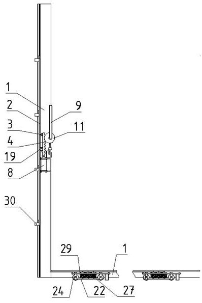
[0023] The hydraulic power boosting and transmission system of lifting sliding door of the present invention, as figure 1 Shown, comprise the handle mechanism that is arranged on the vertical edge of door leaf 1 and the pulley mechanism on the bottom edge, and the hydraulic control mechanism that drives the pulley mechanism by the handle mechanism relies on. The handle mechanism is used for locking and driving the hydraulic control mechanism of the door leaf 1, and the hydraulic control mechanism is used for driving the pulley mechanism, and the pulley mechanism is used for lifting and moving the door leaf 1.

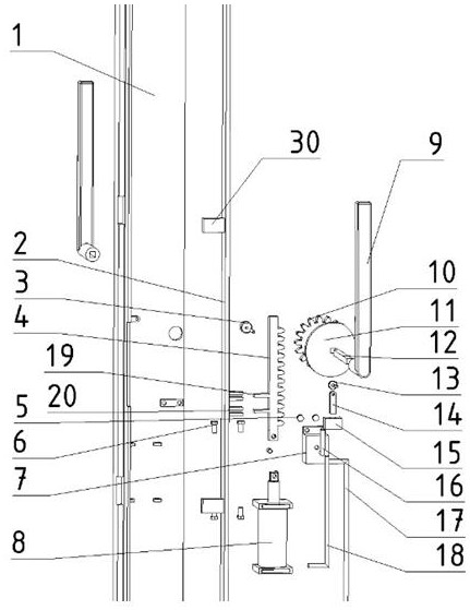
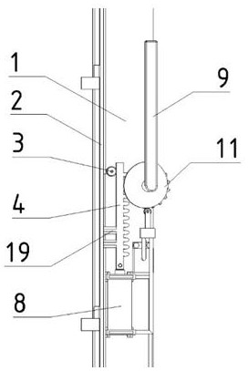
[0024] Such as figure 2 with image 3 , The handle mechanism includes a shaft core 12, a handle 9, a gear 10, a rack 4, a sliding locking bar 2 and a cam 11. Shaft core 12 is equipped with handle 9 at both inside and outside of door leaf 1, and shaft core 12 passes through door leaf hole and installs gear 10 and cam 11 in turn on the inside. The gear 10 meshes with ...


PUM


Abstract

The invention provides a hydraulic force increasing and transmission system for lifting a sliding door. The hydraulic force increasing and transmission system comprises a handle mechanism arranged on the vertical edge of a door leaf, a pulley mechanism arranged on the bottom edge of the door leaf and a hydraulic control mechanism which drives the pulley mechanism to lean on through the handle mechanism; the hydraulic control mechanism is connected with the handle mechanism and the pulley mechanism through a locking hydraulic cylinder and a lifting hydraulic cylinder; the locking hydraulic cylinder is fixed to the door leaf; the lifting hydraulic cylinder is fixed to the pulley mechanism; the handle mechanism is used for locking the door leaf and driving the hydraulic control mechanism; the hydraulic control mechanism is used for driving the pulley mechanism; the pulley mechanism is used for lifting and pushing the door leaf; and the handle mechanism and the pulley mechanism are provided with different hydraulic cylinders, a handle drives a gear and a rack to move so that the hydraulic cylinders can move, and the door leaf can be lifted and lowered. By means of the system, torque needed for lifting the door leaf can be effectively reduced, and the phenomena of jamming and jamming which are extremely prone to happening in a traditional mechanical transmission manner are avoided.

Description

technical field [0001] The invention relates to a hydraulic booster and transmission hardware system for lifting a sliding door, belonging to the technical field of building door and window hardware. Background technique [0002] Sliding doors and windows are a type of doors and windows that do not occupy indoor space and have excellent lighting performance. The bottom of the door leaf is equipped with rollers that are fixed relative to the door leaf and can move along the track at the bottom of the door frame. However, due to the space occupied by the rollers and the sealing structure, the door leaf and the door frame There is a certain gap between them, which affects the sealing of sliding doors and windows, and is gradually eliminated by the market. [0003] The emergence of lifting sliding doors has changed this situation. The lifting sliding door can change the positional relationship between the roller and the door leaf through special hardware, so as to realize the l...

Claims


Application Information

Patent Timeline
Patent Type & Authority Applications(China)
IPC IPC(8): E05F15/57E05D15/16E05B3/00
CPCE05F15/57E05D15/165E05B3/00E05Y2900/132
Inventor 路来骁秦美镇阎玉芹孙捷
Owner SHANDONG JIANZHU UNIV
Learn More