Abrasion compensation mechanism of brake device, brake device and vehicle

A brake device and wear compensation technology, applied in the direction of brake components, brake types, mechanically driven drum brakes, etc., can solve problems such as brake clearance, brake line slack, and inability to brake the vehicle

Pending Publication Date: 2021-07-06
GUANGDONG LOFANDI INTELLIGENT TECH CO LTD
View PDF0 Cites 2 Cited by
  • Summary
  • Abstract
  • Description
  • Claims
  • Application Information

AI Technical Summary

Problems solved by technology

[0006] Aiming at the technical problem that the brake device in the prior art is worn out, the brake gap will be formed, or the brake line will be loose, resulting in the inability to brake the vehicle well, and there are potential safety hazards

Method used


Image

  • Abrasion compensation mechanism of brake device, brake device and vehicle
  • Abrasion compensation mechanism of brake device, brake device and vehicle
  • Abrasion compensation mechanism of brake device, brake device and vehicle

Examples


Embodiment 1

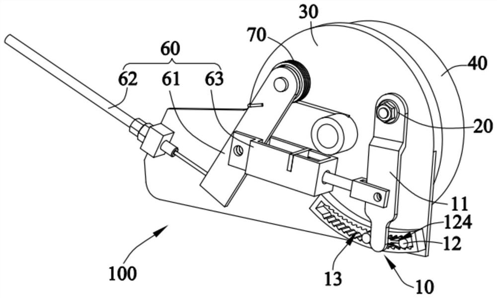
[0074] Please refer to figure 1 with figure 2 . This embodiment provides a wear compensation mechanism 10 of a brake device, which is used to compensate the brake gap after the brakes and / or brake rings of the brake device are worn and produce a brake gap, so as to ensure that the brake and the brake ring can stick together. Combined to ensure the braking effect. Specifically, the wear compensation mechanism 10 of the brake device is used to compensate the angle of the brake transmission mechanism that drives the brakes outward. When the brake device wears, the wear compensation mechanism 10 of the brake device can Compensate an initial deflection angle for the brake transmission mechanism, so that the brake transmission mechanism can be rotated to a larger angle, so that the brake can be further extended outward to a greater distance to compensate for the brake clearance.

[0075] The wear compensation mechanism 10 of the brake device includes an adjustment mechanism 11, ...

Embodiment 2

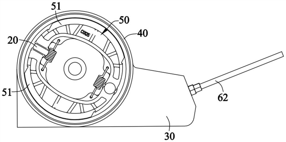
[0089] Please refer to 1 to Figure 11 . This embodiment provides a brake device 100, which includes a housing 30, a brake ring 40, a brake 50, a brake transmission mechanism 20, a wear compensation mechanism of the brake device, and a drive mechanism 60. The brake ring 40 is installed on a vehicle On the wheel, the brake 50 is movably installed on the housing 30, and is set corresponding to the brake ring 40. Specifically, the brake 50 is set in the brake ring 40, and the brake transmission mechanism 20 is movable It is installed on the housing 30 and arranged corresponding to the brake 50 to drive the brake 50 to fit the brake ring 40 . Wherein, the wear compensation mechanism of the brake device adopts the wear compensation mechanism 10 of the brake device in the first embodiment. The driving mechanism 60 is connected with the adjusting mechanism 11 to drive the adjusting mechanism 11 to swing. Wherein, the brake 50 may specifically be a drum brake, an expansion brake, a...

Embodiment 3

[0099] This embodiment provides a vehicle, and the vehicle includes the braking device 100 described in the second embodiment. Specifically, the vehicle may be an electric power-assisted bicycle. Of course, in other embodiments, the brake device 100 can also be applied to any other desired vehicles.

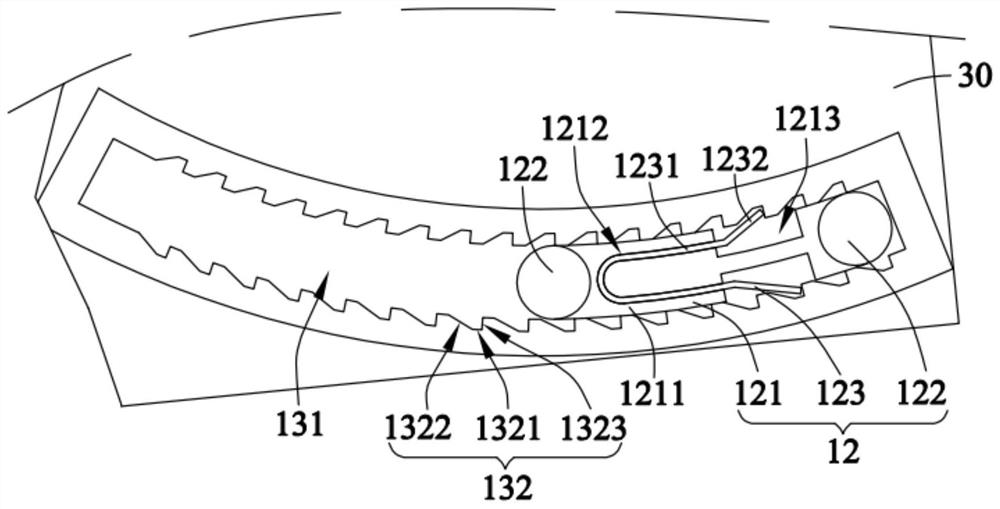
[0100] Compared with the prior art, in the wear compensation mechanism of the brake device provided by the present invention, the adjustment mechanism is connected with the brake transmission mechanism of the brake device and can drive the brake transmission mechanism to rotate in the braking direction or the reset direction The sliding seat is set corresponding to the adjustment mechanism to limit the swing range of the adjustment mechanism; the sliding seat is installed in the chute, and the chute is used to limit the movement of the sliding seat towards the reset direction, And the adjusting mechanism can drive the chute to move towards the braking direction in the chute. Du...


PUM


Abstract

The invention provides an abrasion compensation mechanism of a brake device. The abrasion compensation mechanism comprises an adjusting mechanism, a sliding seat and a sliding groove, and the adjusting mechanism is connected with a brake transmission mechanism of the brake device and can drive the brake transmission mechanism to rotate along a brake direction or a reset direction; the sliding seat is arranged corresponding to the adjusting mechanism and used for limiting the swing range of the adjusting mechanism; and the sliding seat is installed in the sliding groove, the sliding groove is used for limiting the sliding seat to move in the reset direction, and the adjusting mechanism can drive the sliding seat to move in the sliding groove in the brake direction. Meanwhile, the invention further provides a vehicle which comprises the brake device applying the abrasion compensation mechanism of the brake device. Compared with the prior art, the abrasion compensation mechanism of the brake device, the brake device and the vehicle can achieve compensation of the brake clearance, the brake effect is guaranteed, and potential safety hazards are reduced.

Description

technical field [0001] The invention relates to the technical field of vehicle braking, in particular to a wear compensation mechanism of a braking device, a braking device and a vehicle. Background technique [0002] The braking device refers to the action of stopping or reducing the speed of a running vehicle and other means of transportation or machinery, or keeping a stopped vehicle still. Because the structure and performance of the brake device are directly related to the safety of the vehicle and personnel, it is considered as an important safety part of the vehicle and is widely valued. [0003] The brake device in the prior art usually includes a brake and a brake ring. Normally, there is a gap between the brake and the brake ring. The brake rings rub against each other to generate braking force. After the brake device has been used for a period of time, the brake or the brake ring will wear out, resulting in the formation of a brake gap. [0004] However, the ro...

Claims


Application Information

Patent Timeline
Patent Type & Authority Applications(China)
IPC IPC(8): F16D65/60F16D51/22F16D65/56
CPCF16D51/22F16D65/562F16D65/60
Inventor 李激初林杰煌
Owner GUANGDONG LOFANDI INTELLIGENT TECH CO LTD
Why Eureka
Try Eureka